Search the Community
Showing results for tags 'HowTo'.
Found 3 results
-
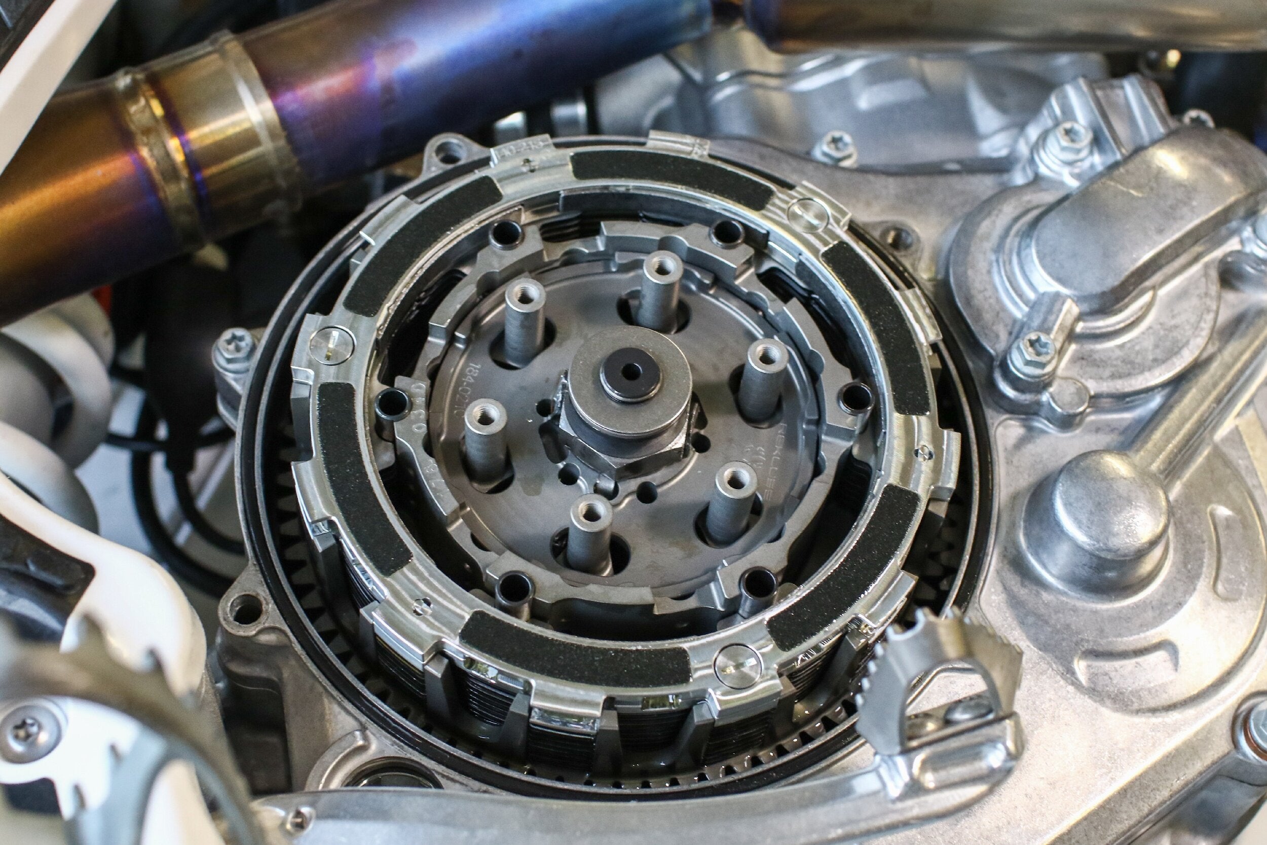 Rekluse auto clutches are high-performance clutches that offer riders many benefits ranging from improved control to increased power transmission; however, like any clutch, it is imperative that they are adequately maintained to ensure long clutch life. Rekluse auto clutches are not overly complicated devices, but they do differ from regular clutches, which means they have different maintenance requirements. In this article, we’ll outline auto clutch maintenance inspections and procedures so next time you inspect your clutch, you’ll be confident and ready to tackle the job. For starters, it’s important to note the key difference between a Rekluse auto clutch and a regular clutch. While Rekluse clutches have many performance enhancing benefits, the main difference between an auto clutch and a regular clutch is the incorporation of Rekluse’s EXP disk. In summary, the EXP disk is the mechanism that allows the clutch to engage and disengage automatically as a function of engine RPM. The EXP disk is the key component within a Rekluse auto clutch and is a crucial point for inspections. Don't have an auto clutch for your bike yet? Find one here! The EXP disk is the key component to Rekluse auto clutches and will be part of auto clutch maintenance. Read on for all the key maintenance details. Click here for our complete guide on everything you need to know about the auto clutch! Maintenance items within this article are broken into two categories: regular maintenance, and periodic maintenance. Regular maintenance are the maintenance items that are essential to perform frequently and ensure you get the most out of your clutch. Periodic maintenance are the maintenance items that are important, but occur less frequently. Periodic maintenance tasks require partial disassembly, whereas most regular maintenance items are performed before operating the machine. We'll cover regular maintenance and periodic maintenance, which may require different levels of disassembly. Regular Maintenance Checking Free Play Gain The most important functional check that can be performed to ensure a Rekluse auto clutch performs reliably throughout its life is to check its free play gain. This check should be performed every time before the machine is ridden. Free play gain that is set incorrectly can result in degraded clutch performance and life. Too little free play gain can result in clutch slip and too much free play gain can result in clutch drag. Checking free play gain is a verification method to assess the installed gap. The “installed gap” is a term used to describe the amount of free space between the clutch pack and pressure plate. The free space is critical because it is what allows the clutch to spin freely until the engagement RPM is reached and the EXP disk expands to engage the clutch fully. Free play gain can be checked using two methods, “the rubber band method” and “the hand method.” Comprehensive instructions on how to check and adjust free play gain can be found in the videos below and in the installation manual. A complete collection of Rekluse support videos can be found HERE. Checking free play gain is a standard practice with Rekluse auto clutches and is a key to ensuring long life and proper performance. It can be done with the supplied rubber band at first to build an understanding, then done by hand once the user feels comfortable. Rubber band and hand methods In both procedures, the bike is warmed up, running, and in neutral. The next step is to take play out of the clutch actuation system by squeezing the clutch lever, whether cable or hydraulic so that the pressure plate springs are on the verge of being compressed. The “hand method,” is done by squeezing the lever and feeling for resistance from the pressure plate, and the “rubber band method” is done by wrapping the supplied rubber band around the handlebar and securing it to the clutch lever. The picture below shows the correct way to secure the rubber band. Once the slack is taken out of the clutch system, quickly rev the engine up to 5000 - 7000 RPM (½ to ¾ throttle). The clutch lever should recede toward the handlebar. Observe the amount of clutch lever movement at the end of the clutch lever. The amount the clutch lever moves is the free play gain. Repeat the revving procedure a couple more times to confirm that free play gain is consistent. Be sure to let the engine return all the way to idle before revving the engine again. For most machines, the correct amount of free play gain is ⅛ inch but can be up to ¼” on select machines. Refer to your installation manual for specific free play gain specifications. If the free play gain falls outside of spec, adjustments to the installed gap should be made before riding the machine. For instructions on how to adjust the installed gap, consult the installation manual provided with your auto clutch. Appropriate Oil Using a suitable oil is key to ensuring peak auto clutch performance. Rekluse has recently developed its own line of oils for street and dirt motorcycle applications and has recommendations on alternatives. Learn more about Rekluse Factory Formulated Oils HERE. Dirt Bikes - Rekluse clutch systems are designed to work with OEM recommended oils, specifically those that meet JASO MA or MA2 standards. In-house oil testing has repeatedly shown that clutch performance is maximized with oils explicitly designed for wet-clutch applications. There are some oils Rekluse does NOT recommend which are JASO-MB oils and automotive oils. JASO-MB oils are not designed for wet-clutches, and automotive oils may contain friction modifiers that negatively affect clutch performance. Street Bikes - Rekluse recommends its Factory Formulated Oils, to use the OEM’s recommended oils, or any high-quality primary oil. Break-in Procedure Any time a new Rekluse auto clutch is installed or rebuilt it is imperative to follow the break-in procedure outlined in the installation manual. The break-in procedure is essential for a couple reasons. First, to ensure proper and smooth EXP disk operation, and second, to ensure the clutch components gradually mate to one another. Proper break-in ultimately allows the clutch to create the most friction during engagement and efficiently transfer power to the ground. A series of roll-on starts are used to break-in Rekluse auto clutches. Be sure to follow the break-in procedure outlined in the installation manual that came with your clutch. This is key to performance and durability! Re-check Free Play Gain Once a Rekluse auto clutch has been broken in it is important that the free play gain is re-checked. As parts mate to one another during break-in, it is possible the installed gap will change and require adjustment. Regular Oil Changes Clutch performance and longevity depend on oil quality. Dirty or degraded oil can easily and quickly increase clutch wear rates. To ensure your clutch operates optimally, Rekluse recommends following your machines OEM specified oil change schedule. Periodic Maintenance and Wear Signs In-depth instructions for checking and servicing Rekluse auto clutches can be found within the supplied installation manual as well as online. Generally speaking, aside from the additional checks and inspections of the EXP disk, clutch inspections and servicing tasks are very similar to regular clutches. The Rekluse website has a complete archive of support documents. Click the image above to find support material for your product and application. Periodic maintenance should be performed per the schedule shown below. The “light” usage range is based on an average rider’s moderate use. The “Heavy” inspection range is based on riding in extreme environments or riding conditions. Use this table as a general guideline to maintenance intervals based on riding style and conditions for the maintenance practices below . As always, each person's situation will vary, so be sure to be sure to perform maintenance as necessary. The following information is provided to highlight essential maintenance inspections and to provide an overview of periodic maintenance activities. EXP Disk Inspection Measure the EXP Disk thickness The thickness of the EXP disk should be measured across the friction pads and compared to the specifications provided in the installation manual. Measure the thickness of your EXP disk on the friction pad and compare to the spec in your Rekluse product manual. If measurements are outside of spec, the EXP bases and Teflon pads should be replaced. Test the EXP Wedges From the inside of the EXP disk, push a pair of wedges opposite one another outward. Once fully extended, release the wedges and observe how they retract. The wedges should return smoothly to their original position. With the EXP disk removed from your machine, push the wedges outward, then release. They should return quickly and smoothly. Consider replacing if there is any stiction or notchiness. If any of the wedges stick, the EXP bases and Teflon pads may need to be replaced. EXP Disk Visual Inspections Inspect the EXP tabs that engage with the clutch basket tangs for signs of hammering and deformation. Check that all friction pads bonded to the EXP plates are in place. Ensure the friction pads are not glazed over. They should appear almost black and have a somewhat rough surface. Pads that are glazed over will have a smooth and shiny appearance. If any glazed pads are encountered the EXP base should be replaced. The first photo shows a new friction pad and the second photo shows a worn friction pad. A worn friction pad indicates the EXP bases should be replaced. Check the EXP assembly for discoloration. Discoloration may be a sign that the clutch overheated. If overheating occurred, the bases and wedges may need to be replaced. With the EXP Disk Disassembled Check the ramps in each EXP base. The ramps are the part of the EXP base that engages with the Teflon pads and allows the wedges to slide in and out of the disk assembly. Ramps that have machining marks or are slightly polished are normal. Ramps with indentations or raised burrs are abnormal, and the EXP base should be replaced. Notice the worn out ramps on the EXP base in the first photo versus the ramps on the new EXP base in the second photo. This is a sign it's time to replace the EXP bases. Check the Teflon pads that reside in the wedges. The Teflon pads should be defect free and sit slightly above the wedge pocket. The Teflon pads can sometimes fall out when the EXP disk is disassembled, so be sure that they are all accounted for before reassembly. Any time the EXP bases are replaced, it is highly recommended that the Teflon pads are replaced as well for best performance. The Teflon pads that sit in the wedges are the contact points for the ramps on the EXP bases. These should also be inspected for wear and replaced as necessary, especially when the EXP bases are being replaced! Drive Plate Inspections Check all drive plates for signs of excess heat buildup by looking for discoloration. Drive plates appearing purple, blue, or black can be an indication that excess heat was built up. This example shows what coloring to look for on the drive plates to know if they've been subject to overheating, and if so, how much. Friction Disk Inspection Check all friction disks for signs of glazing. The friction disks will appear black and rough under normal circumstances. Glazed friction disks will appear smooth and shiny once oil is removed from them. Friction pads on new friction plates have a textured surface and are tan in color. If your fiction plates appear dark or black in color and have a smooth, glossy finish, it's time to replace your friction plates. Operation While there are limited operating restrictions associated with Rekluse auto clutches, there are a couple of noteworthy restrictions that should be adhered to. Do not perform 3rd gear starts - starting in 3rd gear will increase the chances of burning up the clutch and significantly decrease its life. For some street applications, it is crucial to maintain a cruise RPM at or above the recommended cruising RPM outlined in the installation manual. For example, cruise RPM for auto clutches installed on Harley-Davidson motorcycles should be above 2200RPM to ensure the EXP disk is fully engaged. This will ensure clutch slippage and excess heat build-up is avoided. Wrap Up This overview of regular and periodic auto clutch maintenance highlights how easy maintaining an auto clutch can be as well as how important doing so is to ensure the clutch performs optimally throughout its life. Regular maintenance boils down to ensuring break-in is performed according to Rekluse’s recommendations, the free-play gain is checked consistently, the proper oil is utilized, and the oil is changed routinely. Periodic maintenance items consist of a couple of measurements, a functionality check, and several visual inspections to ensure all components are in tip-top shape. If you’re ready to increase the performance of your machine, you can find Rekluse clutches via the Rekluse Make/Model finder or dealer locator. Alternatively, Rekluse customer service can be contacted at 208-426-0659 or by email at customerservice@rekluse.com.
- 3 comments
-
- 1
-

-
- Clutch
- AutoClutch
- (and 3 more)
-
 With years of performance piston experience, JE knows ring operation is just as important as piston quality. Follow along with our complete guide to installing rings on your motorcycle piston(s). The correct installation of the piston rings is an essential aspect of rebuilding any four-stroke engine. This task is perceived by many to be simple. However, there are vital aspects of ring installation that should not be overlooked. Improper installation of the piston rings can result in limited engine life, reduced power, and high oil consumption. In this article, we’ll walk step-by-step through the ring installation process so that the next time you’re rebuilding your engine, you know exactly what to do and what to watch out for. JE now has pistons available for many late model applications. Find the performance you've been looking for. For starters, never attempt ring installation without the appropriate documentation available for reference. At JE Pistons, comprehensive instructions are included with most new piston kits. This ensures the engine builder has the necessary information available to do the job successfully. The machine’s factory service manual should also be on hand throughout the build so that things like torque specs, service limits, and procedures can be referenced. It's important to read and understand any assembly and installation instructions that come with your pistons. These instructions are for representational purposes only and not valid for all JE pistons. Process Overview Before diving into installation details, a quick recap of the process will be helpful to understand what’s to come. Shown below is an outline of the major steps you’ll go through. Measure ring end gap Clean all rings Mark piston where the end gaps should align Install oil rings Install 2nd compression ring Install primary compression ring Verify groove clearance Not sure which piston ring set you need to order? Check out our guide here. In addition to understanding the steps you'll be performing, laying out all the components needed helps stay organized and prepared. Time for a new piston kit? Find one here! Step-by-step Process Measure Ring End Gap Before installing the rings onto the piston, it is imperative that the ring end gaps are checked and verified against the specs provided with the installation instructions or factory service manual, whichever is applicable. If more than one compression ring is used, confirm any design differences between the two by referencing the installation instructions. Chamfers on the inside edge of the ring or different markings at the ring ends are common identifiers used to denote ring differences. Need clarification on all the markings used on JE rings and pistons? Click here. To check the ring end gap, simply install the appropriate ring into the cylinder bore and position it near the top of the bore. Use the depth rod end of a caliper to ensure the ring is square to the bore. Next, use feeler gauges to measure the ring’s end gap. Carefully insert various thickness feeler gauges between the ring ends until the gauge just begins to drag between the ring ends. Note the thickness of the gauge and compare it to the end gap specifications provided. This process can be repeated for any additional compression rings used. The majority of JE's motorcycle rings are pre-gapped, but it's always good practice to check ring end gap for all compression rings prior to installing on the piston. At JE Pistons, the ring end gaps are preset at the factory to fall within spec when installed in healthy cylinders used for normal applications. The end gap of the first compression ring should always be less than that of the second compression ring. If the end gap specs are outside of range, first double check your measurements and verify the cylinder bore is the correct diameter. Assuming no issues are found with the measurements or cylinder bore and the end gap measured is too tight, the rings can be carefully filed. To do so, use a small file and file one end of the ring. Be sure to maintain parallelism to the other ring end as you remove material. Remove small amounts of material and check the end gap periodically so that you don’t remove too much material. If ring end gap does need to be adjusted, evenly file one end of the ring only in small increments and continue to check until it's at the desired spec. Clean All piston rings should be cleaned before being assembled onto the piston. Before cleaning, confirm the ring ends are free of burrs. Any burrs present can carefully be dressed by gently breaking the edge with a small file. Next, use your preferred parts cleaner to wipe down the rings and piston. Make sure your rings are clean and free of any debris or burrs. Mark the Piston Review the instructions provided with your piston kit, or the guidelines provided in your owners manual if no alternate instructions are provided, and note the specified positions of the ring end gaps. Use a marker to mark the edge of the piston crown with the intended ring end positions for the oil control and compression rings. Doing so will help ensure no orientation mistakes are made upon ring installation. Follow the ring end gap orientation instructions for your specific piston(s) and mark the piston so you know where each end gap should end up. Oil Control Ring Installation Modern oil control rings typically utilize a three-piece design and consist of two side rails and an expander ring. Three-piece oil rings can be challenging to install if the ring design and methodology are not understood. The expander ring is the waffle shaped ring and features a stepped edge on the top and bottom of the ring. The side rails are the two small, thin rings which complement the expander. When properly installed, the side rails sit on the top and bottom of the expander ring against its stepped edges. For this reason, the expander ring must be installed first. The other feature of the expander ring worth paying attention to is its ends. Due to the expander’s accordion-like shape, it is possible for the ring ends to overlap in the ring groove. For proper installation, it is imperative that the expander’s ends butt and do not overlap. The ends of the expander ring should be touching, but not overlapping. To install the expander ring, lightly coat it with engine oil. The expander ring is non-directional, so it can be installed in any orientation. Carefully work the ring past the compression ring groove into the oil ring groove. Adjust the expander ring as necessary, so the ring ends are correctly positioned. Ensure the ring ends butt together and don’t overlap. Start by installing the expander ring after lightly coating with oil. The side rails are also non-directional. Lightly lube the side rails then install them on the piston. Make sure the side rails sit correctly against the stepped edge of the expander ring and that their end gaps are positioned properly. Once the side rails have been installed, double-check the end gap positions of all three rings that comprise the oil control ring assembly. Ensure the expander ring’s ends are not overlapped and ensure the assembly moves freely within the oil ring groove. Oil and install the oil expander rails below and above the expander. Be sure they are resting evenly and the end gaps are lined up with the appropriate markings. Compression Ring Installation If the piston utilizes two compression rings, the second compression ring should be installed first. Refer to the installation instructions to determine the proper orientation of the ring before installation. Typically, dots or letters will be marked near the ring end, which denotes the top of the ring. Internal edge features such as chamfers may also be used to identify the ring and its correct orientation. Lightly oil the ring and then carefully work it over the piston into its appropriate groove. Adjust the ring’s end gap position so that it aligns with the mark you made for it on the piston crown. Repeat this process for any remaining compression rings. Install the compression ring(s) in a similar fashion, lightly applying oil and carefully working the ring around the crown of the piston. Be careful not to twist or bend the ring out of shape as it could affect its ability to seal properly. Confirm Groove Clearance Once the compression rings have been installed, the ring-to-groove clearance should be checked. To do so, insert a feeler gauge between the ring and groove. The clearance can be identified by finding the feeler gauge that drags ever so slightly between the ring and groove. Note the groove clearance and compare it to the specification provided in the installation instructions or factory service manual. One of the final measurements to take after the rings have been installed is compression ring to groove clearance. Use a feeler gauge for this and find the size that has slight drag. Compare this spec to what's outlined in your instructions or owner's manual. At this point, ring installation onto the piston is complete, and subsequent steps can be taken to complete the engine build. While installing the piston rings onto the piston is a critical step in the build process, it can be performed by anyone when the proper steps are taken. The process simply requires the correct measurements are taken, cleanliness is ensured, and installation techniques are used. In search of a quality, performance forged piston for your bike? Click here to see what's available for your machine.
- 2 comments
-
- 6
-
-

-
- PistonRings
- Piston
- (and 9 more)
-

 Find out how to relieve an exhaust bridge and drill lubrication holes in 2 stroke applications, so you can get the most out of your piston! When you order a new Wiseco 2-stroke piston and open up the box and read the instructions, you might see something like “follow these steps to drill the lubrication holes.” There’s no doubt that the thought of drilling holes in your new piston can be scary and intimidating. But not to worry! We’ll get you through it right here with all the information you need and a step-by-step. Relieving the exhaust bridge and drilling lubrication holes is a common part of the 2-stroke top end replacement process, but the importance of performing these steps is unrealized by many and neglected too often. Drilling lubrication holes is a simple but important process for many 2 stroke applications. So, what is an exhaust bridge? First things first, not all 2-stroke cylinders have an exhaust bridge. So if your cylinder does not have one, drilling holes in your piston is not necessary. The exhaust bridge is the thin strip of metal that separates the exhaust ports in the cylinder. Whether you look into the exhaust ports through the exhaust outlet or through the cylinder bore, if you see a thin metal wall separating your exhaust ports, that is your exhaust bridge. For the purpose of installing a new Wiseco piston, the area of concern is the edge of the exhaust bridge on the inside of the cylinder bore. The exhaust bridge is the edge of the wall separating the exhaust ports on some 2 stroke cylinders. Why do I need to relieve the exhaust bridge? Now that we know what the exhaust bridge is, it’s important to understand why we feel this machine work is essential to replacing a 2-stroke top end. The most heat in your motor is generated from combustion in the cylinder during normal operation. Specifically, the exhaust port(s) of the cylinder are exposed to the most heat because this is the only way out for the hot gas produced during combustion. This means that under normal running conditions, your piston and your exhaust bridge are constantly under the pressure of extreme heat. Wiseco pistons are made from forged aluminum, which offers more strength and reliability, but also expands faster under heat than an OEM cast piston. The exhaust bridge will also expand more than the rest of the cylinder because it is such a thin structure. The lack of material makes it harder for heat to dissipate before it affects the aluminum and causes expansion. Expansion under heat is normal, but must be compensated for to make sure you get the most life and best performance out of your top end. Relieving the exhaust bridge simply means taking a small amount of material off the face the bridge in order to make room for expansion. If there wasn't any extra clearance, the exhaust bridge would expand past the cylinder wall once your motor heats up. This leads to scoring on the piston as it comes into contact with the exhaust bridge, especially as the piston expands at the same time. Notice the small amount of material taken off of the exhaust bridge, and the blending back into the cylinder. Read below on how to accomplish this. Relieving the Exhaust Bridge Now that we have some understanding established, let’s go through how to get it done. As always, if you don’t feel comfortable doing this work, this can commonly be done by the shop performing your cylinder work. If you have the rights tools, this can be done in the garage on cast iron and steel cylinder bore liners. We recommend using a die grinder with a small sanding roll to gently remove .003” of material off the cylinder wall face of the exhaust bridge. After the material is removed, the machining must be blended with the rest of the cylinder wall at the top and bottom of the exhaust bridge. You want to make sure there’s an easy slope for the piston ring to slide over when entering and exiting the exhaust bridge relief. If your cylinder is lined with Nikasil, this process will not work because that material is too hard. Your exhaust bridge must be relieved before being lined with Nikasil to achieve the same result. Check with the shop you choose for your cylinder work if you are unsure. Why do I need to drill holes in my piston? Relieving the exhaust bridge will make sure there’s no expansion past the cylinder wall, but we still want to make sure we keep the heat as low as possible. With small holes drilled into the skirt of the piston, oil underneath the piston will makes its way through the holes, and lubricate the contact point between the piston and exhaust bridge. Better lubrication means less friction, and less friction means less heat, which is what we want to make sure we don’t have any abnormal wear. Drilling Lubrication Holes Make sure you have the instruction sheet that came with your new piston. This drilling information can also be found there, complete with a visual diagram. Be prepared with your instruction sheet. 1. Install the piston and wrist pin on the connecting rod with one circlip. Make sure the arrow stamped on the dome of the piston is facing the exhaust side of the cylinder. 2. Slide the cylinder over the piston until the cylinder is in its normal position on the crankcase. Temporarily install the piston on the connecting rod and slide the cylinder over the piston. 3. Slowly turn the engine over until the bottom ring groove (or the only ring groove if your piston has only one) on the piston is at the top of the exhaust bridge. You can look through the exhaust port of the cylinder to help know when the piston is in the correct spot. 4. Go through the exhaust port with a pencil and trace a line on the piston skirt for each side of the exhaust bridge. Trace two lines on the piston, one on each side of the exhaust bridge. 5. Once the lines are traced and visible, remove the cylinder and the piston. 6. Start .300” below the bottom ring groove and mark two points .375” apart from each other. Make sure the points are centered horizontally between the two lines you traced. Use the proper measurements to mark 2 points for the holes to be drilled. 7. Drill two holes .060” - .090” in diameter (1/16” or 5/64” drill bit) on your marked points (one hole on each point). Drill holes on your marked points with one of the specified drill bits. 8. Remove all burrs from drilling the lubrication holes. On the inside of the piston, lightly sand with 400-600 grit sand paper. On the outside of the piston, use a ¼” drill bit and twirl it between your fingers over the holes you drilled to break away any edges and imperfections. 9. Wash the cylinder and piston with soap and water, and use compressed air to remove any water and debris. 10. Wipe the cylinder wall with light coat of oil. Whichever 2-cycle oil you normally use is fine. 11. Continue your top end rebuild as normal. This is how your final product should look all cleaned up and deburred. Why doesn't Wiseco pre-drill the holes in the pistons during manufacturing? Some Wiseco two-stroke pistons do come with these lubrication holes pre-drilled. However, there are certain applications that use the same piston across a wide range of model years, but the location of the exhaust ports across those years changes. Therefore, while the piston remains the same, the location of the lubrication holes will vary based the specific year cylinder for certain applications. Want to see the latest in 2-stroke piston technology? Read about the Wiseco 2-Stroke Racer Elite pistons here. See all that Wiseco has to offer for your 2-stroke here.