Search the Community
Showing results for tags 'Maintenance'.
Found 22 results
-
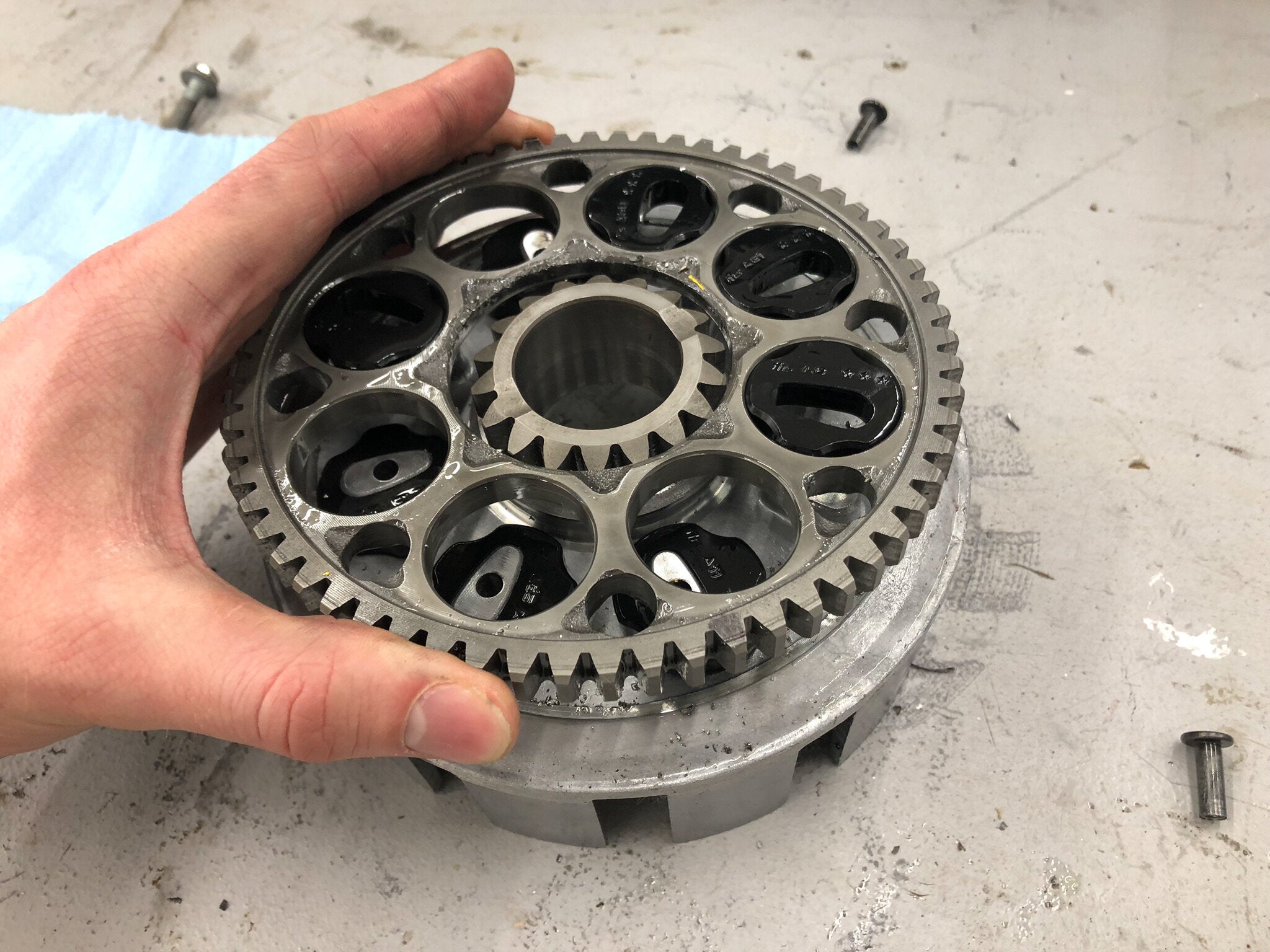 Is your clutch having problems engaging and disengaging? Do you feel inconsistency through the clutch lever when operating the clutch? A worn clutch basket could be the cause. In this article, we’ll look at diagnosing a worn clutch basket, review replacement options, and step through the process of replacing the clutch basket so that the next time you need to tackle the job, you’re well prepared. Time to replace your clutch basket? Read on for a step-by-step on getting your clutch working smoothly again! Diagnosing the Issue Any clutch issues that a machine may have are typically very apparent to the rider because there is a complementary feeling of loss of control of the machine. The machine won’t become outright unrideable; however, subtleties that quickly become annoying will arise when utilizing the clutch. Most notably, modulation of the clutch may become more difficult, and the clutch feel will be inconsistent. Before taking the machine apart, verifying possible simple issues such as clutch cable adjustment and that the engine or gearbox oil has been maintained regularly should be confirmed. To inspect and disassemble the clutch, the procedures outlined in the machine’s factory service manual should be followed. Once the clutch has been removed from the engine, inspecting its condition is straightforward. Double check that any issues you may be experiencing are in fact caused by a worn basket and not from a different culprit, like a clutch cable. Click here for tips on replacing a clutch cable. The basket consists of a series of “fingers,” or “tangs” which mate with the friction discs. The basket fingers drive the friction discs. The friction discs slide out when the clutch is engaged and back in when the clutch is disengaged. Due to this interaction, notching can occur on the edges of the basket fingers. Any notching that can be felt with a pick or a fingernail can be potentially problematic. In terms of clutch basket wear, the main grounds for replacement of the basket are worn and grooved basket fingers. Notching on basket tangs is typically part of normal wear and is the main reason to warrant basket replacement. Replacement Options The clutch basket is a great component to upgrade since it has surfaces such as the basket fingers that are inherently wear surfaces. Selecting a ProX basket, which is significantly stronger and more wear resistant than OE baskets, has a high return on investment in terms of reduced maintenance and improved performance. ProX clutch baskets are precision machined from forged 7075-T6 aluminum, which is one of the strongest alloys on the market. Wear resistance is ensured by utilizing a sophisticated hard anodizing process. A final layer of performance is added in the form of a Teflon coating which seals the basket surfaces and allows the friction discs to slide effortlessly over the clutch basket fingers while in operation. ProX clutch baskets are forged from aluminum, precision machined, and hard anodized and Teflon coated for smooth clutch actuation. The tensile strength of the material combined with the coatings make notching the basket tangs almost impossible. Find ProX clutch components for your bike or ATV here! Tools Required The clutch basket is an assembly of parts including the basket, starter gear, clutch driven gear, dampers, and backing plate. The starter gear is pressed into the clutch basket, and the driven gear, dampers, and backing plate are riveted or screwed in place. When it comes to tools, you’ll need the following, outside of your standard tools used to remove the clutch from the machine: Hydraulic press or vice - capable of exerting up to 8 tons of force. Center punch, drill and drill bits, or grinder, or mill - for removing the rivets Punch and hammer - for driving the rivets out of the assembly Torque wrench and Loctite - for securing the screws in the new basket Fixturing - for adequately supporting the basket while removing and installing the starter gear. The fixturing doesn’t have to be anything fancy, and examples are provided later in this article. There a number of tools required to do the job correctly. For example, having the ability to properly press the starter gear out and in is key to retaining proper function. The Process We’re going to jump into the process post clutch removal and focus on servicing the basket. ProX clutch baskets include new dampers and screws along with instructions for your specific application. The following instructions should be considered supplementary. Mark the backing plate and gear - Use a marker to mark the outside surfaces of the backing plate and gear. Doing so will ensure that these parts are installed in the correct direction when reassembled. Removing the rivets - It is preferable to drill the rivet heads off, however, grinding and milling the heads off are also acceptable options. When drilling, it is best to start by using a center punch to indent the center of the rivet so that the drill bit will not walk. Once center punched, start with a small drill bit and work up to a bit that is slightly smaller in diameter than the rivet itself. Only drill down far enough to remove the head from the rivet. Typically, a depth of 0.040 - 0.080” (1-2mm) below the surface is all that is required to drill out the rivet head. After the rivet head has been drilled out, use a punch and hammer to drive the rivet out of the assembly. The most recommended method to remove the rivets is to drill the heads off then use a punch to remove the rest of the rivet completely. Remove the driven gear - Pull the backplate off before removing the driven gear. Note the orientation of the dampers. Take the driven gear off, then remove the dampers. Make sure you note the orientation of the dampers before removing them all after removing the driven gear. Remove the starter gear - The starter gear utilizes an interference fit with the clutch basket, so it will have to be pressed out. The exact geometry of the starter gear will be model specific. Some starter gears will feature teeth that bite into the clutch basket. Depending on the starter gear geometry and geometry of the clutch basket, it is possible the clutch basket will be destroyed during the removal process. Starter gears will differ depending on the model. Make sure it's adequately supported to press out without damaging the gear. Adequately support the clutch basket around its base so that loads applied will transfer through the center of the basket. Standoffs may need to be utilized to support the basket properly. Select an appropriately sized spacer to place between the starter gear and press. Appropriately sized sockets can serve as suitable spacers. Carefully press the gear out of the hub. There's a good chance the old basket may break when pressing the starter gear out. This is fine, the focus is on not damaging the gear itself. Clean the parts - Remove any clinging material from the starter gear, clean the driven gear and backplate. Install the starter gear - Apply engine oil to the outside of the starter gear. Carefully position it in the center of the new clutch basket. Before pressing it in, be sure to confirm any specific press-in depth requirements outlined in the instructions. Ensure the clutch basket is adequately supported before pressing the gear in place. The press force required to install the gear will be model specific and highlighted in the installation instructions. Be sure to oil the starter gear and note any depth and force specifications for your specific application. On some models, a simple shrink fit is utilized to install the starter gear. When this process is specified, follow the heating instructions for the clutch basket. Once up to temperature, carefully drop in the starter gear. Install the driven gear and dampers - Place the driven gear on the clutch basket noting any orientation requirements previously identified. Install the new dampers in the correct orientation. Install your new dampers in the correct orientation and reinstall the primary gear. Install the backplate - Double check the orientation of the dampers and driven gear. Install the backplate onto the clutch basket, noting any orientation requirements. Torque the backplate screws - Consult the installation instructions for the proper torque specs, apply Loctite if the screws are not pre-Loctite, then tighten in a cross-pattern. Reinstall your back plate with new screws and thread locking compound and torque them to spec. At this point, the clutch basket is ready for service and can be reinstalled on the engine. Refer to your service manual for assembly instructions and specifications to reinstall your clutch and button up the engine. The process of replacing a clutch basket is straightforward and can be executed by anyone so long as the necessary steps are followed and tools are available. We hope this write-up simplifies the job and helps our fellow riders and racers get back out there performing better than before!
- 1 comment
-
- 2
-

-
- Clutch
- ClutchBasket
- (and 3 more)
-
 I have never paid for a brand new dirt bike but might consider it sometime in the future. What's your guys' opinion on maintenance on a newer bike. Is it hard or easy? I have no problem working on dirt bikes at all but have never worked on things like fuel injection, air forks, etc.
 -
I have a 2022 yz250fx, i haven’t done any major maintenance on it (only chain, airfilter, spokes, oil and oil filter…simple maintenance). I am aproaching the 25 hr mark and aside from checking the piston, timing chain, and valves for the first time, is there anything else I should keep my mind on? Thank you and have a wonderful day.
-
 The clutch system is the most important connection between your hand and the rear wheel, as far as controlling the machine. When working properly, most riders don’t give their clutch a second thought. However, the importance of the clutch quickly snaps into focus when there’s a problem with the system. A clutch is an engineering marvel. Imagine you are on the starting line waiting for the gate to drop. You start your bike and pull in the clutch. What follows is a chain reaction of events. A series of moving parts transfer that load down to the clutch, where the pressure plate is pushed away from the clutch pack, basket and inner hub. At that point, there is a disconnection between the transmission and crankshaft. Clutch functionality involves a series of moving parts that are crucial to engine operation. Periodic maintenance, inspection, and replacement will keep your machine running as it should. Shown here is an exploded view from Yamaha of a YZ250 clutch. With the clutch disengaged, you click the shifter into gear. The gate drops, and you quickly release the clutch lever. The clutch springs force the pressure plate to squeeze the friction and drive plates together, causing the clutch basket and inner hub to synchronize. At that point, the energy generated inside the combustion chamber is carried through the transmission and to the countershaft sprocket, which then transfers the load to the rear wheel. Without an operating clutch, you would be sitting on the starting line as the pack raced away. Suffice it to say that your clutch is a vital piece of the overall puzzle. And, like most parts on your bike, it won’t last forever. Fortunately, there are three general indicators that your clutch is not working properly. You don’t need to be deft or dexterous to determine whether your drive system is giving up the ghost. The only necessities are a handful of tools, basic mechanical knowledge, and a good sense of smell. In this article, we delve into the symptoms, causes and solutions for the most common clutch problems so you can get back to riding. Sign #1: Slipping Away Symptoms: A slipping clutch is quickly recognizable when you’re twisting the throttle with reckless abandon while the machine is in gear, yet the rear wheel isn’t rotating in unison with the engine’s rpm. If you’re wound out in third gear and only accelerating at a snail’s pace, then something is wrong. You may also be able to notice a vague feel at the clutch lever. Either of these symptoms suggest that the internal clutch components need to be inspected for wear. Causes: When a clutch is performing optimally, the drive plates and friction plates are pushed together during clutch engagement (i.e. when the clutch lever is let out). The connection causes the rotation of the clutch basket and the inner hub to synchronize and work as one unit. However, as the plates begin to wear out, the clutch plates will slip against each other instead of grabbing. This prevents the transfer of energy from the engine to the transmission. Unfortunately, clutch slipping is inevitable, even if you aren’t a clutch abuser. Clutch plates wear out over time as a result of rubbing when the clutch is engaged. When experiencing clutch slipping, the likely culprit is worn clutch plates. It's time to disassemble and inspect your steel and fiber plates for wear. It is also possible that the clutch springs have lost their tension. When this happens, the springs aren’t strong enough to effectively pull the pressure plate against the clutch pack. Just as with clutch plates, clutch springs do not last forever. Worn clutch springs can also contribute to a slipping clutch. Read on for an explanation on inspecting your clutch springs. Solutions: When you experience clutch slippage, you’ll need to inspect the drive and steel clutch plates, as well as the clutch springs. To quote Dave Sulecki, Wiseco Powersports Engineer, “It’s very easy to access the clutch on all the new bikes. You can literally lay the bike over on its side, pop off the clutch cover, and start inspecting the components.” Using a vernier caliper or micrometer, measure the thickness of the steel (or aluminum) drive plates, and the fiber plates. Consult your owner’s manual to find the recommended specs. Be sure to also check the free length of the clutch springs. It’s a good idea to replace the drive and fiber plates, as well as the clutch springs. The most accurate way to know if your steels and fibers are worn is to measure them and compare the thickness to the recommended spec range in your owner's manual. Similarly, clutch spring free length can be measured to determine if they are outside of spec and need to be replaced. Replacement clutch components—both in individual components and clutch pack kits—are readily available through aftermarket companies like Wiseco. Replacing your fiber and drive plates at the same time is common practice, and when springs are required as well, all these components are available in kits with fibers, plates, and springs in one box. Each kit is built to OEM specifications and far less expensive, and Wiseco clutch springs feature a stiffer rating for a more positive clutch engagement. Replacement clutch components from Wiseco are available in individual packs of steels, fibers, and springs, as well as in clutch pack kits that include all three. Find Wiseco clutch components for your bike or ATV here. Sign #2: Creeping & Bad Smell Symptoms: The machine is emitting a foul burning smell that could strip paint off a wall. The stench might be so pungent that it’s evident after pulling into the pits. Generally, though, the smell is noticeable after removing the clutch cover. You may also notice your bike creeping forward with the clutch pulled in and the transmission in gear, no matter how much you adjust the clutch cable. Causes: Do the sniff test. Pull the clutch cover off. If you smell burnt clutch material, chances are your clutch will need new components. The burnt smell is the result of the clutch heating up. “The parts that burn first are generally the friction plates. It’s a real obvious odor. You’ll know it when you smell it. Visually, you’ll see the heat marks in the drive plates. The friction plates can also become black in color. The best thing to do is check the plates dimensionally against the specifications in your owner’s manual. Make sure you’re within tolerance on width and flatness,” states Sulecki. Burnt friction plates will typically become black in color and burnt drive plates commonly show dark colored wear marks. Solutions: For starters, you’re going to need to replace the oil. Be sure to pay close attention to the recommended service intervals in your owner’s manual. Doing so can extend the life of your clutch. Sulecki adds, “Fresh oil will help keep things lubricated and running cool. Oil does break down from heat and friction over time. In a lot of engines, the clutch shares oil with the transmission and valve train. Oil gets a lot of opportunity to break down quickly. Keep the oil fresh.” However, the damage of a cooked clutch cannot be undone. Clutch plates can warp over time from the heat. Warped plates cause the clutch to disengage unevenly and create all sorts of headaches. You will need to invest in new friction and drive plates, at least. However, heat could also damage the clutch springs, effecting spring tension. Be sure to inspect all your clutch components. If you find your clutch components have been subjected to excessive heat, it's always a good idea to at least replace the drive plates, fibers, and springs (when applicable). Sign #3: Feeling A Drag Symptoms: The clutch lever feels lumpy during clutch engagement/disengagement. Sometimes the lever can feel jerky. These are telltale signs that the clutch basket and/or inner hub is damaged and needs inspection. Causes: If your machine has the OEM/stock clutch basket, it was likely made using a diecast aluminum material. While fairly lightweight, durability is not stellar. “When you cast aluminum, you take molten aluminum and pour it into a mold. Once it has solidified, it gets processed from there into a finished part. When the material is molded it is generally not very dense. You get a lot of voids, porosity, inclusions, and imperfections in the material. The constituents inside the material aren’t bonded tightly against each other,” states Sulecki. The most common wear on cast clutch baskets is notching on the edge of the tangs where the clutch plates engage. The inner hub can be inspected for similar wear. If you see notching like this, it's time for a replacement. Solutions: There are a variety of aftermarket clutch basket options that use different manufacturing processes. Billet is a common alternative to casting, but even that has downfalls. Sulecki explains, “With billet, you’ll start with a cast piece of aluminum. It will generally get compressed a little bit in a forge press or some sort of pressure casting. That’s to condense the material a little tighter. Then the part is machined from the solid piece of metal. It has slightly better properties than a cast part, but not as much as a forged part.” Forging is a very intricate and involved process. It begins with a cast and drawn bar of aluminum material, which is then smashed until all of the molecules are bonded to each other. This makes the material much denser and creates what engineers refer to as feature aligned grain flow. Basically all of the grains in the material are forced to flow up through the features–particularly the tangs on the clutch basket and stanchions on the inner hub–for greater strength. All of the material properties improve–from tensile to fatigue to ultimate strength. Ductility is also improved, meaning the material can bend before it breaks. Cast and billet constructed clutch baskets are susceptible to wear. This is why Wiseco forges their clutch baskets in house before machining them, achieving greater tensile strength and wear resistance. Sulecki adds, “The denser material is very resistant to impact and fatigue, which are two critical components of a clutch basket. Impact is caused by the clutch plates as they drive against the tangs on the clutch basket. Clutch plates will actually start to create indentations on a stock cast part, and dimples on a billet basket. In turn, the plates can’t slide smoothly across the width of the tab as you pull in the clutch lever to disengage the clutch. A forged clutch basket’s resistance to impact means that it will not develop notches in the tangs.” Suffice it to say that forging is the superior material for clutch basket durability and lasting performance. Check out all the technical details on Wiseco clutch baskets here. The forged material creates much greater resistance to impact from the clutch plates during operation, providing a seemingly lifetime solution to tang notching. To cap it off, Wiseco hard coat anodizes and coats their forged clutch baskets with Teflon. Hard coat anodizing aids in wear and abrasion resistance, as well as improves lubricity and corrosion resistance. Teflon coating is the last process. It helps fulfill the wear resistance and lubricity that Wiseco requires for their clutch baskets. Hard coat anodizing and teflon coating finish off Wiseco clutch baskets for ultimate wear resistance and smooth operation. Find a Wiseco clutch basket for your machine here. Lifetime Guarantee It’s interesting to note that Wiseco has been manufacturing forged clutch baskets, pressure plates and inner hubs for years, but this all-too-important detail has flown under the radar. “Our forged clutch basket is the best product we make that nobody knows about,” says Sulecki. The performance-driven powersports magnate is so resolute in the durability of their forged clutch baskets that they offer a lifetime guarantee against notching and breakage. What does that mean? You’ll buy it once and never have to worry about it again. Related Reading: How to Replace the Clutch Basket in your Motorcycle
-
- 10
-

-
-
- Clutch
- Maintenance
- (and 8 more)
-
So we just rebuilt my carb, stock jetting kit. Everything went great. We dial in the fuel air mixture screw, the idle screw and then I ride it a bit. Then I put it away for a few minutes, I come back to start it. Kick 1, nothing, kick 2, nothing, (flooded maybe?) I thought, kick 3 BOOOOOM a huge loud pop from the exhuast. Kick 4 nothing. I bump start it, and now it starts and rides fine. What was that pop guys? Did it hurt anything in my bike? It is a ttr125
-
Hey guys, I was working on changing the tube in my front tire today and when I took my front wheel off to inspect it I ran into this.... Im not much of a mechanic and this is my first bike, it's a 2007 XR650L, but in that first photo i feel like you can see rust or something forming around the bearing I'm guessin. Is this bearing bad? This is the only bearing that looks like this, but I don't know if I should change out both sides or just this side? Do I need to change the seal also when I change the bearing? Thanks for any help!!
-
Okay so I have just got a 2003 Yamaha wrf450, it's my first proper bike and just want to know what I have to do to keep it running good, I'm buying a hour metre to go on it but would like to know when to service it or do what ever I need to, the person I got it off said that it had top end rebuild 6 hours ago, just want to know before I start riding it so I know it won't stuff up on me, I know that the start motor goes on them and I think this ones gone I'll be replacing it with an 04 model starter but if anyone could give me information on servicing or anything let me know please and thank you. Andrew.
-
So I'm changing gear oil on my Ktm 85 sx, and the manual says that I have to fill up with 15w 50 gear oil, but we only have 10w 30. Do I need to use that exact oil or is that only if a wanna keep it top notch? And would it be fine if I just fill it up for a couple rides, and change after like two rides when I have new oil that complies with the specifications?
-
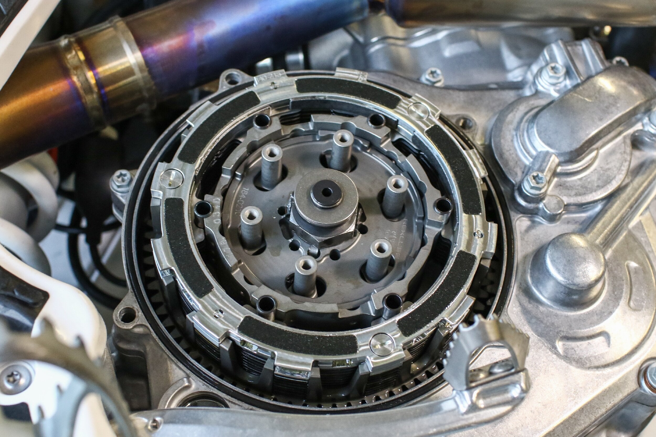 Rekluse auto clutches are high-performance clutches that offer riders many benefits ranging from improved control to increased power transmission; however, like any clutch, it is imperative that they are adequately maintained to ensure long clutch life. Rekluse auto clutches are not overly complicated devices, but they do differ from regular clutches, which means they have different maintenance requirements. In this article, we’ll outline auto clutch maintenance inspections and procedures so next time you inspect your clutch, you’ll be confident and ready to tackle the job. For starters, it’s important to note the key difference between a Rekluse auto clutch and a regular clutch. While Rekluse clutches have many performance enhancing benefits, the main difference between an auto clutch and a regular clutch is the incorporation of Rekluse’s EXP disk. In summary, the EXP disk is the mechanism that allows the clutch to engage and disengage automatically as a function of engine RPM. The EXP disk is the key component within a Rekluse auto clutch and is a crucial point for inspections. Don't have an auto clutch for your bike yet? Find one here! The EXP disk is the key component to Rekluse auto clutches and will be part of auto clutch maintenance. Read on for all the key maintenance details. Click here for our complete guide on everything you need to know about the auto clutch! Maintenance items within this article are broken into two categories: regular maintenance, and periodic maintenance. Regular maintenance are the maintenance items that are essential to perform frequently and ensure you get the most out of your clutch. Periodic maintenance are the maintenance items that are important, but occur less frequently. Periodic maintenance tasks require partial disassembly, whereas most regular maintenance items are performed before operating the machine. We'll cover regular maintenance and periodic maintenance, which may require different levels of disassembly. Regular Maintenance Checking Free Play Gain The most important functional check that can be performed to ensure a Rekluse auto clutch performs reliably throughout its life is to check its free play gain. This check should be performed every time before the machine is ridden. Free play gain that is set incorrectly can result in degraded clutch performance and life. Too little free play gain can result in clutch slip and too much free play gain can result in clutch drag. Checking free play gain is a verification method to assess the installed gap. The “installed gap” is a term used to describe the amount of free space between the clutch pack and pressure plate. The free space is critical because it is what allows the clutch to spin freely until the engagement RPM is reached and the EXP disk expands to engage the clutch fully. Free play gain can be checked using two methods, “the rubber band method” and “the hand method.” Comprehensive instructions on how to check and adjust free play gain can be found in the videos below and in the installation manual. A complete collection of Rekluse support videos can be found HERE. Checking free play gain is a standard practice with Rekluse auto clutches and is a key to ensuring long life and proper performance. It can be done with the supplied rubber band at first to build an understanding, then done by hand once the user feels comfortable. Rubber band and hand methods In both procedures, the bike is warmed up, running, and in neutral. The next step is to take play out of the clutch actuation system by squeezing the clutch lever, whether cable or hydraulic so that the pressure plate springs are on the verge of being compressed. The “hand method,” is done by squeezing the lever and feeling for resistance from the pressure plate, and the “rubber band method” is done by wrapping the supplied rubber band around the handlebar and securing it to the clutch lever. The picture below shows the correct way to secure the rubber band. Once the slack is taken out of the clutch system, quickly rev the engine up to 5000 - 7000 RPM (½ to ¾ throttle). The clutch lever should recede toward the handlebar. Observe the amount of clutch lever movement at the end of the clutch lever. The amount the clutch lever moves is the free play gain. Repeat the revving procedure a couple more times to confirm that free play gain is consistent. Be sure to let the engine return all the way to idle before revving the engine again. For most machines, the correct amount of free play gain is ⅛ inch but can be up to ¼” on select machines. Refer to your installation manual for specific free play gain specifications. If the free play gain falls outside of spec, adjustments to the installed gap should be made before riding the machine. For instructions on how to adjust the installed gap, consult the installation manual provided with your auto clutch. Appropriate Oil Using a suitable oil is key to ensuring peak auto clutch performance. Rekluse has recently developed its own line of oils for street and dirt motorcycle applications and has recommendations on alternatives. Learn more about Rekluse Factory Formulated Oils HERE. Dirt Bikes - Rekluse clutch systems are designed to work with OEM recommended oils, specifically those that meet JASO MA or MA2 standards. In-house oil testing has repeatedly shown that clutch performance is maximized with oils explicitly designed for wet-clutch applications. There are some oils Rekluse does NOT recommend which are JASO-MB oils and automotive oils. JASO-MB oils are not designed for wet-clutches, and automotive oils may contain friction modifiers that negatively affect clutch performance. Street Bikes - Rekluse recommends its Factory Formulated Oils, to use the OEM’s recommended oils, or any high-quality primary oil. Break-in Procedure Any time a new Rekluse auto clutch is installed or rebuilt it is imperative to follow the break-in procedure outlined in the installation manual. The break-in procedure is essential for a couple reasons. First, to ensure proper and smooth EXP disk operation, and second, to ensure the clutch components gradually mate to one another. Proper break-in ultimately allows the clutch to create the most friction during engagement and efficiently transfer power to the ground. A series of roll-on starts are used to break-in Rekluse auto clutches. Be sure to follow the break-in procedure outlined in the installation manual that came with your clutch. This is key to performance and durability! Re-check Free Play Gain Once a Rekluse auto clutch has been broken in it is important that the free play gain is re-checked. As parts mate to one another during break-in, it is possible the installed gap will change and require adjustment. Regular Oil Changes Clutch performance and longevity depend on oil quality. Dirty or degraded oil can easily and quickly increase clutch wear rates. To ensure your clutch operates optimally, Rekluse recommends following your machines OEM specified oil change schedule. Periodic Maintenance and Wear Signs In-depth instructions for checking and servicing Rekluse auto clutches can be found within the supplied installation manual as well as online. Generally speaking, aside from the additional checks and inspections of the EXP disk, clutch inspections and servicing tasks are very similar to regular clutches. The Rekluse website has a complete archive of support documents. Click the image above to find support material for your product and application. Periodic maintenance should be performed per the schedule shown below. The “light” usage range is based on an average rider’s moderate use. The “Heavy” inspection range is based on riding in extreme environments or riding conditions. Use this table as a general guideline to maintenance intervals based on riding style and conditions for the maintenance practices below . As always, each person's situation will vary, so be sure to be sure to perform maintenance as necessary. The following information is provided to highlight essential maintenance inspections and to provide an overview of periodic maintenance activities. EXP Disk Inspection Measure the EXP Disk thickness The thickness of the EXP disk should be measured across the friction pads and compared to the specifications provided in the installation manual. Measure the thickness of your EXP disk on the friction pad and compare to the spec in your Rekluse product manual. If measurements are outside of spec, the EXP bases and Teflon pads should be replaced. Test the EXP Wedges From the inside of the EXP disk, push a pair of wedges opposite one another outward. Once fully extended, release the wedges and observe how they retract. The wedges should return smoothly to their original position. With the EXP disk removed from your machine, push the wedges outward, then release. They should return quickly and smoothly. Consider replacing if there is any stiction or notchiness. If any of the wedges stick, the EXP bases and Teflon pads may need to be replaced. EXP Disk Visual Inspections Inspect the EXP tabs that engage with the clutch basket tangs for signs of hammering and deformation. Check that all friction pads bonded to the EXP plates are in place. Ensure the friction pads are not glazed over. They should appear almost black and have a somewhat rough surface. Pads that are glazed over will have a smooth and shiny appearance. If any glazed pads are encountered the EXP base should be replaced. The first photo shows a new friction pad and the second photo shows a worn friction pad. A worn friction pad indicates the EXP bases should be replaced. Check the EXP assembly for discoloration. Discoloration may be a sign that the clutch overheated. If overheating occurred, the bases and wedges may need to be replaced. With the EXP Disk Disassembled Check the ramps in each EXP base. The ramps are the part of the EXP base that engages with the Teflon pads and allows the wedges to slide in and out of the disk assembly. Ramps that have machining marks or are slightly polished are normal. Ramps with indentations or raised burrs are abnormal, and the EXP base should be replaced. Notice the worn out ramps on the EXP base in the first photo versus the ramps on the new EXP base in the second photo. This is a sign it's time to replace the EXP bases. Check the Teflon pads that reside in the wedges. The Teflon pads should be defect free and sit slightly above the wedge pocket. The Teflon pads can sometimes fall out when the EXP disk is disassembled, so be sure that they are all accounted for before reassembly. Any time the EXP bases are replaced, it is highly recommended that the Teflon pads are replaced as well for best performance. The Teflon pads that sit in the wedges are the contact points for the ramps on the EXP bases. These should also be inspected for wear and replaced as necessary, especially when the EXP bases are being replaced! Drive Plate Inspections Check all drive plates for signs of excess heat buildup by looking for discoloration. Drive plates appearing purple, blue, or black can be an indication that excess heat was built up. This example shows what coloring to look for on the drive plates to know if they've been subject to overheating, and if so, how much. Friction Disk Inspection Check all friction disks for signs of glazing. The friction disks will appear black and rough under normal circumstances. Glazed friction disks will appear smooth and shiny once oil is removed from them. Friction pads on new friction plates have a textured surface and are tan in color. If your fiction plates appear dark or black in color and have a smooth, glossy finish, it's time to replace your friction plates. Operation While there are limited operating restrictions associated with Rekluse auto clutches, there are a couple of noteworthy restrictions that should be adhered to. Do not perform 3rd gear starts - starting in 3rd gear will increase the chances of burning up the clutch and significantly decrease its life. For some street applications, it is crucial to maintain a cruise RPM at or above the recommended cruising RPM outlined in the installation manual. For example, cruise RPM for auto clutches installed on Harley-Davidson motorcycles should be above 2200RPM to ensure the EXP disk is fully engaged. This will ensure clutch slippage and excess heat build-up is avoided. Wrap Up This overview of regular and periodic auto clutch maintenance highlights how easy maintaining an auto clutch can be as well as how important doing so is to ensure the clutch performs optimally throughout its life. Regular maintenance boils down to ensuring break-in is performed according to Rekluse’s recommendations, the free-play gain is checked consistently, the proper oil is utilized, and the oil is changed routinely. Periodic maintenance items consist of a couple of measurements, a functionality check, and several visual inspections to ensure all components are in tip-top shape. If you’re ready to increase the performance of your machine, you can find Rekluse clutches via the Rekluse Make/Model finder or dealer locator. Alternatively, Rekluse customer service can be contacted at 208-426-0659 or by email at customerservice@rekluse.com.
- 3 comments
-
- 1
-
-
- Clutch
- AutoClutch
- (and 3 more)
-

How to Check & Adjust Valve Clearance on Your Dirt Bike
Billy@JEPistons posted an article in Articles
.jpg.82410982eb8e70b004990467af57d1ac.jpg) Checking and adjusting valves is considered routine maintenance on high-performance four-stroke engines used throughout the powersports industry. Valve clearance inspections are not hard to perform and are well within the capability of most owners. However, there are tips and tricks that can make the job go smoother and yield better results. The JE Pistons team has been building and testing engines for over 70 years, and as a result, we know what it takes to do the job to a high standard. With years of experience in four-stroke engines of all types, JE is no stranger to the valve adjustments and maintenance. Whether you own a dirt bike, ATV, street bike, or any other four-stroke equipped machine, chances are your owner’s manual outlines when your engine’s valve clearances should be checked. Depending on the application, the inspection interval may vary from 15 hours to 15,000 miles. Checking clearances at the specified intervals is incredibly important to ensure the engine continues to run optimally and lasts a long time. Also, as a rule of thumb, anytime the top-end of the engine is disassembled, it is best practice to check valve clearances. Any time you have the top end apart to replace the piston, you should check your valve clearance and adjust as necessary. Before servicing your engine, you will need your machine’s factory service manual. The service manual is required because it specifies the required clearances, torque specs, and other information imperative to performing the task. The outline we’re providing should be considered supplemental to the information in your service manual and is in no way a comprehensive substitute. To tackle this job, you’ll typically need the following tools and supplies: Lash/feeler gauges Metric wrenches Metric sockets Clean rags or towels Screwdrivers Caliper In most cases, specialty tools aren’t utilized, however, if they are, you’ll find that information in your service manual. A critical tool to measuring valve clearance is a set of feeler gauges. Since the engine is going to be partially opened up and exposed, it is best to work on a clean machine. If your machine is dirty, take the time to clean it thoroughly so the risk of contaminating the engine with debris is lessened. Prioritize cleaning the cylinder head cover and surrounding area. Chances are you're not working on a new bike, so be sure the area around the cam cover is clean to avoid unwanted debris. We’ll begin outlining the procedure with the removal of the cylinder head cover. You’ll likely need to remove your seat, fuel tank and various other components before this. These items should be easy to remove, and your service manual should provide sufficient guidance. When removing the cylinder head cover, be extremely careful not to allow dirt to fall into the cylinder head. If you're working on an engine still in the bike, you'll need to remove your seat and tank, along with any other components hindering your access to the cam cover. Next, the valvetrain will need to be positioned so that the clearances can be checked. Most service manuals specify setting the valvetrain so that the piston is at top dead center (TDC) on the compression stroke. Setting the valvetrain at this position ensures that the cam, or cams, are on their base circles and that neither the intake or exhaust valves are open. The base circle of the cam is the circular portion of the cam which does not influence valve lift. As an aside and for future reference, while it is sensible to follow the service manuals recommendations on setting the piston position and engine stroke when the engine is assembled, it is not necessary, especially when working on an engine that is being rebuilt. Checking valve clearance can also be accomplished with the cylinder head removed from the engine and positioning the cam lobes opposite the lifter buckets to ensure the clearance measurements are taken with the cam on its base circle. Whether the head is still on the engine or you're working on it separately, be sure the engine is either at TDC or the cam lobes are resting somewhere on their base circle and not applying pressure to the buckets like they would when opening valves. Your service manual outlines the required procedure to set the engine on its compression stroke at TDC. Most engines have mating alignment marks on the crankshaft and engine case as well as the cam gear and cylinder head. It is imperative that you know and understand how to utilize these reference points because they are used to correctly set the cam timing after any valve clearance adjustments have been made. Once you’ve positioned the cams correctly, valve clearance measurements can be made using lash (feeler) gauges. Lash gauge measurements can be tricky due to surrounding geometry and inexperience on the user’s part. To obtain the most accurate measurement, it is essential that the lash gauge is inserted between the cam and lifter bucket as close to parallel as possible. To facilitate parallel entry, bend the lash gauges as necessary so that their tips can easily slide between the cam and lifter bucket. Measure valve clearance by inserting your lash gauge(s) between the cam lobe and lifter bucket. Accurate lash gauge measurements are subjective because they are based on feel. Ideally, the most accurate valve clearance measurements are obtained when the lash gauge passes between the cam and lifter bucket with a slight drag. Gauges that pass through easily or must be forced through should be considered too thin or too thick, respectively. When this occurs, other gauges should be tried, or, if you’re between sizes, the average of the two should be utilized as the valve clearance. Begin by the using the gauge equal to the median recommended valve clearance measurement in your manual. You may have to move up or down a couple sizes until you find the size that slides between the cam lobe and bucket with a slight drag. Record this measurement for each valve. After each of the intake and exhaust valve clearances has been recorded, they should be compared to the service specifications outlined in your service manual. If the valve clearances fall within the manufacturer’s recommended range, no further work is required. However, if the clearances are outside of the specifications, determining what adjustments need to be made is the next step. To do this, unless the current valve shim thicknesses are known, the cylinder head will have to be disassembled so that the shims can be removed and measured. Follow the necessary procedures outlined in your service manual to slacken the cam chain, remove the cam cap, cams, and lifter buckets. When removing the cam cap, be sure to follow any recommended removal/tensioning sequences. Once the cam chain is free, use a piece of wire to secure it to the cylinder head. If it happens to fall in the chaincase, a pen magnet can be used to fish it out. Be sure to slacken the cam chain before attempting removal. Remove the camshaft(s) and secure the cam chain so it doesn't fall in the cases. To remove the lifter buckets, a pen magnet or valve lapping tool are both excellent aids to utilize. When extracting the lifter buckets from their bores, be very careful and keep tabs on whether or not the valve shim sticks to the underside of the bucket. Oil underneath the lifter buckets makes sticking shims a common occurrence. Use a pen magnet or lapping tool to remove the buckets. Be careful of shims that may stick on the underside of buckets. Through engine operation, the lifter buckets mate to their respective bores so they should never be mixed around. To help keep track of things, draw out a simple cylinder head diagram on a piece of paper so that the lifter buckets and all the measurements can be tracked. Proceed to remove any remaining valve shims from the cylinder head. Once the valve shims have been removed, measure the shim thicknesses and the diameter of shims used. Drawing a simple diagram can help you keep track of what buckets and shims came from where. Once everything is removed, confirm your shim measurements. To determine what valve shim adjustments should be made, a simple formula is used: New Shim Thickness = Recorded Clearance - Specified Clearance + Old Shim Thickness Calculate the necessary new shim thicknesses for all the clearances that are out of spec. Valve shims are available from most OEMs, but helpful shim kits that come with an assortment of sizes are also available from the aftermarket. Before sourcing shims, you’ll need to determine the diameter of the shim you need because there are a handful of different shim diameters used within the industry. Shown below are the standard shim diameters. Size (mm) 7.48 (Japanese) 9.48 (Japanese) 8.90 (KTM) 10.00 (KTM) Shim assortment kits are available from various aftermarket suppliers, just be sure you know what shim diameter your machine takes before ordering. This kit was sourced from ProX Racing Parts. When calculating what new shim thicknesses are required, it is best to target the specified clearance on the upper end of the prescribed clearance range. This is advised because valve clearances usually diminish over time. Valve shims are available in 0.025mm increments, so the shims that can be utilized will also influence the new clearances that can be achieved. Once you have the correct shims in hand, the valvetrain can be reassembled. Use engine oil to lubricate the valve shims and carefully install them. The lifter buckets should also be lubed before installation. When inserting the lifter buckets into their respective bores, ensure that the buckets bottom on the shims and at no point comes back up. If the bucket comes back up upon installation, occasionally the shim will stick to it and become displaced. The engine can quickly be severely damaged if the shim is not seated correctly between the valve stem and lifter bucket. Using engine oil and assembly lube when reassembling your shims, buckets, and cams helps prevent premature wear and also helps your shims stay in place while re-inserting buckets. Pay close attention to your service manual during installation of the cams and when setting cam timing. Double check that the crankshaft is in its correct position. If you’re working on a twin cam engine, it is best to install the camshaft that resides opposite of the chain tensioner first (typically the exhaust cam), pull the chain taught from the crankshaft, orient the cam gear correctly, and then wrap the chain around the gear. Once this is accomplished, the remaining cam can be oriented correctly and the chain wrapped around it. Double check orientation of all components and that timing has been set correctly. Be sure to use engine oil to lube the cam bearing bores upon installation. Make sure your timing marks on your crankshaft are lined up, then reinstall your cam(s). It's important to make sure the timing marks on the crankshaft and cam(s) remain lined up simultaneously when reinstalling the cam chain. Click here for a more in-depth guide to setting cam timing. When installing the cam cap, ensure the torque specs and sequences outlined in your service manual are followed. Deviations from either can cause the cam bearings to wear prematurely. Once the cams have been secured, use lash gauges to confirm the new valve clearances match the clearances that were calculated. Any deviations that are found should be carefully scrutinized because they may be indicative of calculation errors or shims that are not seated correctly. If there is a hint of a problem at this point, it is imperative that it is thoroughly understood and corrected before proceeding. Be sure to follow the correct torque sequence and specifications when re-installing cam caps. Assuming everything checks out, the cam chain can be tensioned. Follow the procedure outlined in your service manual to do so. Once the tension has been set, rotate the engine through at least four complete revolutions. Doing so will help the automatic chain tensioners to set the correct initial tension and confirm that the engine has been timed correctly. Position the piston at TDC on the compression stroke and check that all timing features on the crank and cams remain in their specified positions. Complete the job by carefully reinstalling the cylinder head cover, making sure to torque those bolts in a star sequence to recommended specs. Once the rest of the machine is buttoned up, it’s time to get back to riding! More Tech Articles from JE Pistons
Checking and adjusting valves is considered routine maintenance on high-performance four-stroke engines used throughout the powersports industry. Valve clearance inspections are not hard to perform and are well within the capability of most owners. However, there are tips and tricks that can make the job go smoother and yield better results. The JE Pistons team has been building and testing engines for over 70 years, and as a result, we know what it takes to do the job to a high standard. With years of experience in four-stroke engines of all types, JE is no stranger to the valve adjustments and maintenance. Whether you own a dirt bike, ATV, street bike, or any other four-stroke equipped machine, chances are your owner’s manual outlines when your engine’s valve clearances should be checked. Depending on the application, the inspection interval may vary from 15 hours to 15,000 miles. Checking clearances at the specified intervals is incredibly important to ensure the engine continues to run optimally and lasts a long time. Also, as a rule of thumb, anytime the top-end of the engine is disassembled, it is best practice to check valve clearances. Any time you have the top end apart to replace the piston, you should check your valve clearance and adjust as necessary. Before servicing your engine, you will need your machine’s factory service manual. The service manual is required because it specifies the required clearances, torque specs, and other information imperative to performing the task. The outline we’re providing should be considered supplemental to the information in your service manual and is in no way a comprehensive substitute. To tackle this job, you’ll typically need the following tools and supplies: Lash/feeler gauges Metric wrenches Metric sockets Clean rags or towels Screwdrivers Caliper In most cases, specialty tools aren’t utilized, however, if they are, you’ll find that information in your service manual. A critical tool to measuring valve clearance is a set of feeler gauges. Since the engine is going to be partially opened up and exposed, it is best to work on a clean machine. If your machine is dirty, take the time to clean it thoroughly so the risk of contaminating the engine with debris is lessened. Prioritize cleaning the cylinder head cover and surrounding area. Chances are you're not working on a new bike, so be sure the area around the cam cover is clean to avoid unwanted debris. We’ll begin outlining the procedure with the removal of the cylinder head cover. You’ll likely need to remove your seat, fuel tank and various other components before this. These items should be easy to remove, and your service manual should provide sufficient guidance. When removing the cylinder head cover, be extremely careful not to allow dirt to fall into the cylinder head. If you're working on an engine still in the bike, you'll need to remove your seat and tank, along with any other components hindering your access to the cam cover. Next, the valvetrain will need to be positioned so that the clearances can be checked. Most service manuals specify setting the valvetrain so that the piston is at top dead center (TDC) on the compression stroke. Setting the valvetrain at this position ensures that the cam, or cams, are on their base circles and that neither the intake or exhaust valves are open. The base circle of the cam is the circular portion of the cam which does not influence valve lift. As an aside and for future reference, while it is sensible to follow the service manuals recommendations on setting the piston position and engine stroke when the engine is assembled, it is not necessary, especially when working on an engine that is being rebuilt. Checking valve clearance can also be accomplished with the cylinder head removed from the engine and positioning the cam lobes opposite the lifter buckets to ensure the clearance measurements are taken with the cam on its base circle. Whether the head is still on the engine or you're working on it separately, be sure the engine is either at TDC or the cam lobes are resting somewhere on their base circle and not applying pressure to the buckets like they would when opening valves. Your service manual outlines the required procedure to set the engine on its compression stroke at TDC. Most engines have mating alignment marks on the crankshaft and engine case as well as the cam gear and cylinder head. It is imperative that you know and understand how to utilize these reference points because they are used to correctly set the cam timing after any valve clearance adjustments have been made. Once you’ve positioned the cams correctly, valve clearance measurements can be made using lash (feeler) gauges. Lash gauge measurements can be tricky due to surrounding geometry and inexperience on the user’s part. To obtain the most accurate measurement, it is essential that the lash gauge is inserted between the cam and lifter bucket as close to parallel as possible. To facilitate parallel entry, bend the lash gauges as necessary so that their tips can easily slide between the cam and lifter bucket. Measure valve clearance by inserting your lash gauge(s) between the cam lobe and lifter bucket. Accurate lash gauge measurements are subjective because they are based on feel. Ideally, the most accurate valve clearance measurements are obtained when the lash gauge passes between the cam and lifter bucket with a slight drag. Gauges that pass through easily or must be forced through should be considered too thin or too thick, respectively. When this occurs, other gauges should be tried, or, if you’re between sizes, the average of the two should be utilized as the valve clearance. Begin by the using the gauge equal to the median recommended valve clearance measurement in your manual. You may have to move up or down a couple sizes until you find the size that slides between the cam lobe and bucket with a slight drag. Record this measurement for each valve. After each of the intake and exhaust valve clearances has been recorded, they should be compared to the service specifications outlined in your service manual. If the valve clearances fall within the manufacturer’s recommended range, no further work is required. However, if the clearances are outside of the specifications, determining what adjustments need to be made is the next step. To do this, unless the current valve shim thicknesses are known, the cylinder head will have to be disassembled so that the shims can be removed and measured. Follow the necessary procedures outlined in your service manual to slacken the cam chain, remove the cam cap, cams, and lifter buckets. When removing the cam cap, be sure to follow any recommended removal/tensioning sequences. Once the cam chain is free, use a piece of wire to secure it to the cylinder head. If it happens to fall in the chaincase, a pen magnet can be used to fish it out. Be sure to slacken the cam chain before attempting removal. Remove the camshaft(s) and secure the cam chain so it doesn't fall in the cases. To remove the lifter buckets, a pen magnet or valve lapping tool are both excellent aids to utilize. When extracting the lifter buckets from their bores, be very careful and keep tabs on whether or not the valve shim sticks to the underside of the bucket. Oil underneath the lifter buckets makes sticking shims a common occurrence. Use a pen magnet or lapping tool to remove the buckets. Be careful of shims that may stick on the underside of buckets. Through engine operation, the lifter buckets mate to their respective bores so they should never be mixed around. To help keep track of things, draw out a simple cylinder head diagram on a piece of paper so that the lifter buckets and all the measurements can be tracked. Proceed to remove any remaining valve shims from the cylinder head. Once the valve shims have been removed, measure the shim thicknesses and the diameter of shims used. Drawing a simple diagram can help you keep track of what buckets and shims came from where. Once everything is removed, confirm your shim measurements. To determine what valve shim adjustments should be made, a simple formula is used: New Shim Thickness = Recorded Clearance - Specified Clearance + Old Shim Thickness Calculate the necessary new shim thicknesses for all the clearances that are out of spec. Valve shims are available from most OEMs, but helpful shim kits that come with an assortment of sizes are also available from the aftermarket. Before sourcing shims, you’ll need to determine the diameter of the shim you need because there are a handful of different shim diameters used within the industry. Shown below are the standard shim diameters. Size (mm) 7.48 (Japanese) 9.48 (Japanese) 8.90 (KTM) 10.00 (KTM) Shim assortment kits are available from various aftermarket suppliers, just be sure you know what shim diameter your machine takes before ordering. This kit was sourced from ProX Racing Parts. When calculating what new shim thicknesses are required, it is best to target the specified clearance on the upper end of the prescribed clearance range. This is advised because valve clearances usually diminish over time. Valve shims are available in 0.025mm increments, so the shims that can be utilized will also influence the new clearances that can be achieved. Once you have the correct shims in hand, the valvetrain can be reassembled. Use engine oil to lubricate the valve shims and carefully install them. The lifter buckets should also be lubed before installation. When inserting the lifter buckets into their respective bores, ensure that the buckets bottom on the shims and at no point comes back up. If the bucket comes back up upon installation, occasionally the shim will stick to it and become displaced. The engine can quickly be severely damaged if the shim is not seated correctly between the valve stem and lifter bucket. Using engine oil and assembly lube when reassembling your shims, buckets, and cams helps prevent premature wear and also helps your shims stay in place while re-inserting buckets. Pay close attention to your service manual during installation of the cams and when setting cam timing. Double check that the crankshaft is in its correct position. If you’re working on a twin cam engine, it is best to install the camshaft that resides opposite of the chain tensioner first (typically the exhaust cam), pull the chain taught from the crankshaft, orient the cam gear correctly, and then wrap the chain around the gear. Once this is accomplished, the remaining cam can be oriented correctly and the chain wrapped around it. Double check orientation of all components and that timing has been set correctly. Be sure to use engine oil to lube the cam bearing bores upon installation. Make sure your timing marks on your crankshaft are lined up, then reinstall your cam(s). It's important to make sure the timing marks on the crankshaft and cam(s) remain lined up simultaneously when reinstalling the cam chain. Click here for a more in-depth guide to setting cam timing. When installing the cam cap, ensure the torque specs and sequences outlined in your service manual are followed. Deviations from either can cause the cam bearings to wear prematurely. Once the cams have been secured, use lash gauges to confirm the new valve clearances match the clearances that were calculated. Any deviations that are found should be carefully scrutinized because they may be indicative of calculation errors or shims that are not seated correctly. If there is a hint of a problem at this point, it is imperative that it is thoroughly understood and corrected before proceeding. Be sure to follow the correct torque sequence and specifications when re-installing cam caps. Assuming everything checks out, the cam chain can be tensioned. Follow the procedure outlined in your service manual to do so. Once the tension has been set, rotate the engine through at least four complete revolutions. Doing so will help the automatic chain tensioners to set the correct initial tension and confirm that the engine has been timed correctly. Position the piston at TDC on the compression stroke and check that all timing features on the crank and cams remain in their specified positions. Complete the job by carefully reinstalling the cylinder head cover, making sure to torque those bolts in a star sequence to recommended specs. Once the rest of the machine is buttoned up, it’s time to get back to riding! More Tech Articles from JE Pistons- 2 comments
-
- 6
-
-
-
- Valves
- Maintenance
- (and 8 more)
-
.jpg.91a1379aba0cfb75d154e92ffe0307b1.jpg) Periodically inspecting and replacing the chain on your motorcycle or ATV is part of regular maintenance. Here, we go over steps and key tips for replacing your worn out chain with a new one. The necessity to periodically replace the chain on off-road machines comes as a byproduct of operating in harsh environments containing dirt, mud, sand, etc. On road machines aren’t exempt from this maintenance task either, however, their replacement intervals are longer. Replacing your machine’s chain isn’t a tough job if you’re well equipped and prepared to take on the task. Replacing your machine's chain is part of normal maintenance and should not be neglected. To start, it is essential to have a copy of your machine’s factory service manual. Within the service manual, you’ll find specific instructions and torque specifications that may be required to complete the job. For example, if either of the sprockets requires replacement, it is imperative the nuts and bolts that secure them are torqued to the outlined specifications. Before purchasing a new chain, you’ll want to confirm that the sprockets are in good condition. Pairing a new chain to worn sprockets will accelerate the rate of chain wear and be counterproductive. You’ll also want to inspect components that come in contact with the chain such as chain slides and rollers. Replacing these components at the same time as the chain is advantageous. Inspect your sprockets before beginning the new chain install process. Notice how the grooves in the worn sprocket are asymmetrical in comparison to the new sprocket. Inspections Sprocket condition can be checked visually by looking at the sprocket teeth. Sprocket teeth take on a hook shape when they become worn, and in severe cases, shorten and round off when service has been severely neglected. If funds allow, it’s always best practice to replace both sprockets when replacing your chain. This will allow for the most life possible out of your drive system. Don't let a worn sprocket ruin your new chain. Replace them when you replace your chain. The condition of the chain can be assessed by putting the bike on a center stand. Rotate the rear wheel and visually inspect the chain’s condition. As you rotate, feel the chain for tight spots or links that are stuck together. Attempt to pull the chain away from the rearmost part of the rear sprocket. If the chain can be pulled off the rear sprocket by a half sprocket tooth or more, it is time for a replacement. Similarly, if the chain moves significantly side to side when pushed and pulled on the sprocket, wear has occurred. Check your chain's wear level by attempting to pull it away from the back of the rear sprocket. If it's half a tooth or more, it's time for a replacement. Check any chain slides to ensure they have ample life left. Rotate chain rollers to ensure they spin freely. Check your chain rollers and sliders as well. These are normal wear items, and they should be replaced when they show signs of excessive wear. ProX also offer OEM replacement chain rollers in addition to chains and sprockets. Chain Sizing and Options Off and on-road chains used for powersports applications come in various sizes based on chain pitch and length. Before purchasing a new chain, you’ll need to confirm the appropriate pitch and size for your machine. Chain pitch defines the distance between the chain pins. Common pitch options are shown in the table below along with their corresponding dimensions. There are a couple of ways to determine the type of chain your machine utilizes. First, your factory service manual should contain this information. This is usually found in the rear wheel specification table. Second, most chain manufacturers denote the chain’s pitch on the side of the chain. You can obtain the chain’s length simply by counting the number of chain links it has. Many chain manufacturers will indicate the pitch on the links of the chain itself. Once you’ve determined the chain pitch and length you need, you’re ready to order. When it comes to ordering, you’ll need to decide on the type of master link connection you want and whether the chain is a standard chain or a sealed chain. The most common chains in dirt bike and ATV applications are 420 (for minis) and 520. ProX offers both sizes of chains. ProX 520MX chains are available in both standard and X-ring, in standard and gold finishes. The gold finish is the result of a rust-resistant coating. ProX chains are made in Japan from high-quality Japanese steel. These chains come with master link style connections, which is the most common in modern off-road applications. 520 is the most common size for modern off-road motorcycles, and 420 is a common size for minis. Master Link Connection Clip Type - Clip type connections are widespread nowadays and are notable for their ease of installation. Clip type master links are not quite as strong as rivet type. However, they can be installed with no special tools. Rivet Type - Rivet type master links require a special rivet tool to install but offer a more permanent connection. A clip type master link. Chain Seals The difference between a standard chain and a sealed chain is that the former does not use any type of seal to retain chain lubricant. Sealed chains, often referred to as O-ring chains, utilize O-rings or similar variants to retain lubricant which helps reduce wear and prolong chain life. There are different styles of O-ring chains available, such as ProX’s X-ring chains. ProX’s X-ring chains are a sealed O-ring chain but have less O-ring surface area touching the link surfaces to reduce the drag in comparison to a normal O-ring chain. The advantage is in the design of the O-rings themselves. CLICK HERE for a full explanation of the differences between standard and O-ring chains to help you decide which one type is right for you. Tools To replace a chain that utilizes a clip type master link, you’ll need the following: Pliers for pressing on the chain plate or master link plate pressing tool. Pliers will also be used to install the master link clip. Flat blade screwdriver for removing the master link clip. Grinder, punch, and hammer, or chain breaker tool to adjust chain length. To replace a chain that utilizes a rivet type master link, you’ll need the following: Chain rivet tool for installing the master link. Grinder, punch, and hammer, or chain breaker tool to adjust chain length and to remove the old chain. Ensure you have the proper tools before beginning your chain replacement job. Chain Removal On chains utilizing a clip type master link, chain removal is as simple as prying off the master link clip and removing the master link. Through use, the master link plate usually wears enough so that it can easily be slid off the link. If the master link plate is tight, the master link should be driven out by using a punch and hammer or chain break tool. For clip style chains, one easy way to remove the master link clip is to use a pair of pliers to push the clip off by using the chain pin for leverage. Chains utilizing rivet master links will require pin grinding so that one of the links can be removed. Grind the rivets that retain one of the links flat, then use a punch and hammer or chain break tool to push the chain link out. Chain Installation If necessary, resize the chain to your machine by removing the appropriate number of chain links. Remember to count the chain links of the old chain to establish the length of the new chain. Don’t lay them side by side and try to set the length because the chain stretch that occurred in the old chain will lead to an incorrect chain length of the new chain. Chains almost always need to be sized (have links removed). Your manual should specify the required number of links, but sizing it up on the bike will give you a good idea if your rear axle will be in the recommended position. Chain links can be removed by carefully grinding the rivet flat to the chain side plate, then driving the pin out with a punch and hammer. Alternatively, a chain break tool can be used. Sizing the chain can be done by grinding and punching, but the easiest way to remove links is to use a tool made specifically for the job. Loosen the rear axle nut and slacken the chain adjusters. The new chain will necessitate this since it has not worn or stretched. Position the two chain ends on the rear sprocket. Next, install the master link whether clip or rivet type. Be sure to include the o-rings when installing sealed chains. Clip Type Master Link Install Once the master link has been installed, install another pair of o-rings (on sealed chains) followed by the master link plate. The master link plate will need to be pressed onto the master link. Use a pair of pliers to squeeze the plate onto the master link. Press the plate on far enough so that the grooves that retain the master link clip become exposed. A pair of small c-clamps can sometimes be helpful when installing the plate, or a master link plate installation tool can be utilized. Place your master link through the wheel side of the chain so the clip will face out. Next, press the master link plate on the outside of the link. Using a pair of pliers to press the plate past the grooves on the chain pins should be sufficient. Next, install the master link clip. The master link clip is directional and should be oriented so that the closed end of the clip leads the direction of rotation. By orienting the clip this way, should the clip hit an object during operation, it will not become dislodged from the master link. To install the master link clip, position it in its mating grooves on the master link. Use pliers to seat the clip fully in its grooves. Now, install the master link clip. The closed end of the clip should lead the direction of forward rotation of the wheel. Use a pair of pliers with leverage against the pin to fully snap the clip in place. Be sure it is fully seated. Rivet Type Master Link Install To install a rivet type master link, you will need a master link rivet tool. It’s recommend to follow the instructions provided with the tool to perform the rivet operation. The chain manufacturer will also provide specifications which govern the appropriate amount of flare to add when deforming the rivets. Setting Chain Slack Once the master link has been installed the chain tension should be adjusted so that the machine has the appropriate amount of chain slack. Your machine’s service manual will outline how to measure the chain slack and define the slack range. Most manufacturers recommend measuring chain slack with the bike on a center stand. Slack is then measured by pulling up on the chain near the center of the swingarm and measuring its displacement. Most dirt bikes require 30 - 60mm (1.18 - 2.36 inches) of chain slack. Carefully manipulate the chain adjusters so that they tension the chain evenly and align with the same reference points from side to side. Once chain slack is correctly set, torque the rear axle nut to the specification outlined in your service manual. Once installed, adjust your chain slack to the recommended spec using the axle block adjusters. Secure the lock nut when finished, then torque the rear axle nut to spec. Post Installation Tips Most chains are pre-stretched to reduce the amount of initial chain stretch that occurs once the chain is put in use, however, it is never a bad idea to keep an eye on the chain slack after the first few rides. New chains come pre-lubricated from the factory. However, you should always ensure your chain stays lubricated throughout its life. Lubing your chain before or after every ride, especially muddy or rainy ones, should become habitual. Find ProX chain and other components for your bike HERE!
Periodically inspecting and replacing the chain on your motorcycle or ATV is part of regular maintenance. Here, we go over steps and key tips for replacing your worn out chain with a new one. The necessity to periodically replace the chain on off-road machines comes as a byproduct of operating in harsh environments containing dirt, mud, sand, etc. On road machines aren’t exempt from this maintenance task either, however, their replacement intervals are longer. Replacing your machine’s chain isn’t a tough job if you’re well equipped and prepared to take on the task. Replacing your machine's chain is part of normal maintenance and should not be neglected. To start, it is essential to have a copy of your machine’s factory service manual. Within the service manual, you’ll find specific instructions and torque specifications that may be required to complete the job. For example, if either of the sprockets requires replacement, it is imperative the nuts and bolts that secure them are torqued to the outlined specifications. Before purchasing a new chain, you’ll want to confirm that the sprockets are in good condition. Pairing a new chain to worn sprockets will accelerate the rate of chain wear and be counterproductive. You’ll also want to inspect components that come in contact with the chain such as chain slides and rollers. Replacing these components at the same time as the chain is advantageous. Inspect your sprockets before beginning the new chain install process. Notice how the grooves in the worn sprocket are asymmetrical in comparison to the new sprocket. Inspections Sprocket condition can be checked visually by looking at the sprocket teeth. Sprocket teeth take on a hook shape when they become worn, and in severe cases, shorten and round off when service has been severely neglected. If funds allow, it’s always best practice to replace both sprockets when replacing your chain. This will allow for the most life possible out of your drive system. Don't let a worn sprocket ruin your new chain. Replace them when you replace your chain. The condition of the chain can be assessed by putting the bike on a center stand. Rotate the rear wheel and visually inspect the chain’s condition. As you rotate, feel the chain for tight spots or links that are stuck together. Attempt to pull the chain away from the rearmost part of the rear sprocket. If the chain can be pulled off the rear sprocket by a half sprocket tooth or more, it is time for a replacement. Similarly, if the chain moves significantly side to side when pushed and pulled on the sprocket, wear has occurred. Check your chain's wear level by attempting to pull it away from the back of the rear sprocket. If it's half a tooth or more, it's time for a replacement. Check any chain slides to ensure they have ample life left. Rotate chain rollers to ensure they spin freely. Check your chain rollers and sliders as well. These are normal wear items, and they should be replaced when they show signs of excessive wear. ProX also offer OEM replacement chain rollers in addition to chains and sprockets. Chain Sizing and Options Off and on-road chains used for powersports applications come in various sizes based on chain pitch and length. Before purchasing a new chain, you’ll need to confirm the appropriate pitch and size for your machine. Chain pitch defines the distance between the chain pins. Common pitch options are shown in the table below along with their corresponding dimensions. There are a couple of ways to determine the type of chain your machine utilizes. First, your factory service manual should contain this information. This is usually found in the rear wheel specification table. Second, most chain manufacturers denote the chain’s pitch on the side of the chain. You can obtain the chain’s length simply by counting the number of chain links it has. Many chain manufacturers will indicate the pitch on the links of the chain itself. Once you’ve determined the chain pitch and length you need, you’re ready to order. When it comes to ordering, you’ll need to decide on the type of master link connection you want and whether the chain is a standard chain or a sealed chain. The most common chains in dirt bike and ATV applications are 420 (for minis) and 520. ProX offers both sizes of chains. ProX 520MX chains are available in both standard and X-ring, in standard and gold finishes. The gold finish is the result of a rust-resistant coating. ProX chains are made in Japan from high-quality Japanese steel. These chains come with master link style connections, which is the most common in modern off-road applications. 520 is the most common size for modern off-road motorcycles, and 420 is a common size for minis. Master Link Connection Clip Type - Clip type connections are widespread nowadays and are notable for their ease of installation. Clip type master links are not quite as strong as rivet type. However, they can be installed with no special tools. Rivet Type - Rivet type master links require a special rivet tool to install but offer a more permanent connection. A clip type master link. Chain Seals The difference between a standard chain and a sealed chain is that the former does not use any type of seal to retain chain lubricant. Sealed chains, often referred to as O-ring chains, utilize O-rings or similar variants to retain lubricant which helps reduce wear and prolong chain life. There are different styles of O-ring chains available, such as ProX’s X-ring chains. ProX’s X-ring chains are a sealed O-ring chain but have less O-ring surface area touching the link surfaces to reduce the drag in comparison to a normal O-ring chain. The advantage is in the design of the O-rings themselves. CLICK HERE for a full explanation of the differences between standard and O-ring chains to help you decide which one type is right for you. Tools To replace a chain that utilizes a clip type master link, you’ll need the following: Pliers for pressing on the chain plate or master link plate pressing tool. Pliers will also be used to install the master link clip. Flat blade screwdriver for removing the master link clip. Grinder, punch, and hammer, or chain breaker tool to adjust chain length. To replace a chain that utilizes a rivet type master link, you’ll need the following: Chain rivet tool for installing the master link. Grinder, punch, and hammer, or chain breaker tool to adjust chain length and to remove the old chain. Ensure you have the proper tools before beginning your chain replacement job. Chain Removal On chains utilizing a clip type master link, chain removal is as simple as prying off the master link clip and removing the master link. Through use, the master link plate usually wears enough so that it can easily be slid off the link. If the master link plate is tight, the master link should be driven out by using a punch and hammer or chain break tool. For clip style chains, one easy way to remove the master link clip is to use a pair of pliers to push the clip off by using the chain pin for leverage. Chains utilizing rivet master links will require pin grinding so that one of the links can be removed. Grind the rivets that retain one of the links flat, then use a punch and hammer or chain break tool to push the chain link out. Chain Installation If necessary, resize the chain to your machine by removing the appropriate number of chain links. Remember to count the chain links of the old chain to establish the length of the new chain. Don’t lay them side by side and try to set the length because the chain stretch that occurred in the old chain will lead to an incorrect chain length of the new chain. Chains almost always need to be sized (have links removed). Your manual should specify the required number of links, but sizing it up on the bike will give you a good idea if your rear axle will be in the recommended position. Chain links can be removed by carefully grinding the rivet flat to the chain side plate, then driving the pin out with a punch and hammer. Alternatively, a chain break tool can be used. Sizing the chain can be done by grinding and punching, but the easiest way to remove links is to use a tool made specifically for the job. Loosen the rear axle nut and slacken the chain adjusters. The new chain will necessitate this since it has not worn or stretched. Position the two chain ends on the rear sprocket. Next, install the master link whether clip or rivet type. Be sure to include the o-rings when installing sealed chains. Clip Type Master Link Install Once the master link has been installed, install another pair of o-rings (on sealed chains) followed by the master link plate. The master link plate will need to be pressed onto the master link. Use a pair of pliers to squeeze the plate onto the master link. Press the plate on far enough so that the grooves that retain the master link clip become exposed. A pair of small c-clamps can sometimes be helpful when installing the plate, or a master link plate installation tool can be utilized. Place your master link through the wheel side of the chain so the clip will face out. Next, press the master link plate on the outside of the link. Using a pair of pliers to press the plate past the grooves on the chain pins should be sufficient. Next, install the master link clip. The master link clip is directional and should be oriented so that the closed end of the clip leads the direction of rotation. By orienting the clip this way, should the clip hit an object during operation, it will not become dislodged from the master link. To install the master link clip, position it in its mating grooves on the master link. Use pliers to seat the clip fully in its grooves. Now, install the master link clip. The closed end of the clip should lead the direction of forward rotation of the wheel. Use a pair of pliers with leverage against the pin to fully snap the clip in place. Be sure it is fully seated. Rivet Type Master Link Install To install a rivet type master link, you will need a master link rivet tool. It’s recommend to follow the instructions provided with the tool to perform the rivet operation. The chain manufacturer will also provide specifications which govern the appropriate amount of flare to add when deforming the rivets. Setting Chain Slack Once the master link has been installed the chain tension should be adjusted so that the machine has the appropriate amount of chain slack. Your machine’s service manual will outline how to measure the chain slack and define the slack range. Most manufacturers recommend measuring chain slack with the bike on a center stand. Slack is then measured by pulling up on the chain near the center of the swingarm and measuring its displacement. Most dirt bikes require 30 - 60mm (1.18 - 2.36 inches) of chain slack. Carefully manipulate the chain adjusters so that they tension the chain evenly and align with the same reference points from side to side. Once chain slack is correctly set, torque the rear axle nut to the specification outlined in your service manual. Once installed, adjust your chain slack to the recommended spec using the axle block adjusters. Secure the lock nut when finished, then torque the rear axle nut to spec. Post Installation Tips Most chains are pre-stretched to reduce the amount of initial chain stretch that occurs once the chain is put in use, however, it is never a bad idea to keep an eye on the chain slack after the first few rides. New chains come pre-lubricated from the factory. However, you should always ensure your chain stays lubricated throughout its life. Lubing your chain before or after every ride, especially muddy or rainy ones, should become habitual. Find ProX chain and other components for your bike HERE! -
I have a 2004 honda crf450r with probably over 500 hours on it but im not sure since it has no meter. I Bought it when I was 16 back in 2013 which means I've had it for around 7 years. It was pretty well taken care of and had the motor top and bottom rebuilt probably 15 hours before I got it. I have been riding it every weekend possible ever since I got it. I ride 95% trail with a very tiny bit of road just to get to another trail. I don't ride hard all the time, but I would say 70% of the time I would consider hard riding, wide open throttle, lots of shifting, racing other bikes. I have hit the rev limiter like maybe 2 times ever since I've had it. Oil changed probably every 3 rides or so. There's a strange soft ticking coming from the bike rope end and my guess is valves since I have never checked them once. It seems to be running very strong still, never has burned oil, and starts cold every time around the 3rd kick. Starts hot on the first kick. My question is when do I rebuild this thing? Should I be worried even if I can fix the slight tick in the top? It doesn't show any signs of breaking down on me but I feel like I'm on a grenade. I dont want to get it inspected by anyone and if it comes to it I'll be rebuilding on my own.
-
I can't find one single video online on how to replace the countershaft, can anyone link me one film me one or explain how please
-
#Husqvarna #CR125 #2-Stroke #Maintenance #Advice
-

 Find out how to relieve an exhaust bridge and drill lubrication holes in 2 stroke applications, so you can get the most out of your piston! When you order a new Wiseco 2-stroke piston and open up the box and read the instructions, you might see something like “follow these steps to drill the lubrication holes.” There’s no doubt that the thought of drilling holes in your new piston can be scary and intimidating. But not to worry! We’ll get you through it right here with all the information you need and a step-by-step. Relieving the exhaust bridge and drilling lubrication holes is a common part of the 2-stroke top end replacement process, but the importance of performing these steps is unrealized by many and neglected too often. Drilling lubrication holes is a simple but important process for many 2 stroke applications. So, what is an exhaust bridge? First things first, not all 2-stroke cylinders have an exhaust bridge. So if your cylinder does not have one, drilling holes in your piston is not necessary. The exhaust bridge is the thin strip of metal that separates the exhaust ports in the cylinder. Whether you look into the exhaust ports through the exhaust outlet or through the cylinder bore, if you see a thin metal wall separating your exhaust ports, that is your exhaust bridge. For the purpose of installing a new Wiseco piston, the area of concern is the edge of the exhaust bridge on the inside of the cylinder bore. The exhaust bridge is the edge of the wall separating the exhaust ports on some 2 stroke cylinders. Why do I need to relieve the exhaust bridge? Now that we know what the exhaust bridge is, it’s important to understand why we feel this machine work is essential to replacing a 2-stroke top end. The most heat in your motor is generated from combustion in the cylinder during normal operation. Specifically, the exhaust port(s) of the cylinder are exposed to the most heat because this is the only way out for the hot gas produced during combustion. This means that under normal running conditions, your piston and your exhaust bridge are constantly under the pressure of extreme heat. Wiseco pistons are made from forged aluminum, which offers more strength and reliability, but also expands faster under heat than an OEM cast piston. The exhaust bridge will also expand more than the rest of the cylinder because it is such a thin structure. The lack of material makes it harder for heat to dissipate before it affects the aluminum and causes expansion. Expansion under heat is normal, but must be compensated for to make sure you get the most life and best performance out of your top end. Relieving the exhaust bridge simply means taking a small amount of material off the face the bridge in order to make room for expansion. If there wasn't any extra clearance, the exhaust bridge would expand past the cylinder wall once your motor heats up. This leads to scoring on the piston as it comes into contact with the exhaust bridge, especially as the piston expands at the same time. Notice the small amount of material taken off of the exhaust bridge, and the blending back into the cylinder. Read below on how to accomplish this. Relieving the Exhaust Bridge Now that we have some understanding established, let’s go through how to get it done. As always, if you don’t feel comfortable doing this work, this can commonly be done by the shop performing your cylinder work. If you have the rights tools, this can be done in the garage on cast iron and steel cylinder bore liners. We recommend using a die grinder with a small sanding roll to gently remove .003” of material off the cylinder wall face of the exhaust bridge. After the material is removed, the machining must be blended with the rest of the cylinder wall at the top and bottom of the exhaust bridge. You want to make sure there’s an easy slope for the piston ring to slide over when entering and exiting the exhaust bridge relief. If your cylinder is lined with Nikasil, this process will not work because that material is too hard. Your exhaust bridge must be relieved before being lined with Nikasil to achieve the same result. Check with the shop you choose for your cylinder work if you are unsure. Why do I need to drill holes in my piston? Relieving the exhaust bridge will make sure there’s no expansion past the cylinder wall, but we still want to make sure we keep the heat as low as possible. With small holes drilled into the skirt of the piston, oil underneath the piston will makes its way through the holes, and lubricate the contact point between the piston and exhaust bridge. Better lubrication means less friction, and less friction means less heat, which is what we want to make sure we don’t have any abnormal wear. Drilling Lubrication Holes Make sure you have the instruction sheet that came with your new piston. This drilling information can also be found there, complete with a visual diagram. Be prepared with your instruction sheet. 1. Install the piston and wrist pin on the connecting rod with one circlip. Make sure the arrow stamped on the dome of the piston is facing the exhaust side of the cylinder. 2. Slide the cylinder over the piston until the cylinder is in its normal position on the crankcase. Temporarily install the piston on the connecting rod and slide the cylinder over the piston. 3. Slowly turn the engine over until the bottom ring groove (or the only ring groove if your piston has only one) on the piston is at the top of the exhaust bridge. You can look through the exhaust port of the cylinder to help know when the piston is in the correct spot. 4. Go through the exhaust port with a pencil and trace a line on the piston skirt for each side of the exhaust bridge. Trace two lines on the piston, one on each side of the exhaust bridge. 5. Once the lines are traced and visible, remove the cylinder and the piston. 6. Start .300” below the bottom ring groove and mark two points .375” apart from each other. Make sure the points are centered horizontally between the two lines you traced. Use the proper measurements to mark 2 points for the holes to be drilled. 7. Drill two holes .060” - .090” in diameter (1/16” or 5/64” drill bit) on your marked points (one hole on each point). Drill holes on your marked points with one of the specified drill bits. 8. Remove all burrs from drilling the lubrication holes. On the inside of the piston, lightly sand with 400-600 grit sand paper. On the outside of the piston, use a ¼” drill bit and twirl it between your fingers over the holes you drilled to break away any edges and imperfections. 9. Wash the cylinder and piston with soap and water, and use compressed air to remove any water and debris. 10. Wipe the cylinder wall with light coat of oil. Whichever 2-cycle oil you normally use is fine. 11. Continue your top end rebuild as normal. This is how your final product should look all cleaned up and deburred. Why doesn't Wiseco pre-drill the holes in the pistons during manufacturing? Some Wiseco two-stroke pistons do come with these lubrication holes pre-drilled. However, there are certain applications that use the same piston across a wide range of model years, but the location of the exhaust ports across those years changes. Therefore, while the piston remains the same, the location of the lubrication holes will vary based the specific year cylinder for certain applications. Want to see the latest in 2-stroke piston technology? Read about the Wiseco 2-Stroke Racer Elite pistons here. See all that Wiseco has to offer for your 2-stroke here.
 -
Recently I took my linkage off and while it was off I moved the tire and swingarm through its swing to see for myself how tight the chain was at the tightest spot. I was able to move it about .75 -1" up and down when set to spec. Which I understand is fine. My question is it "looks" tight sitting next to other bikes and compared to pictures as others appear to droop a lot which is why I was wondering. Those must be too loose no, to have such a droop? I know every bike is a little different but mine is a CRF450RL and compared to other CRF450s with same setup I'd bet most I see are too loose. The goal should be as tight as possible without binding as swingarm swings no? The spec for me is 55-60mm measured at rear of chain guide lifting chain. This puts it at .75-1" of up and down play when front sprocket swingarm pivot and rear sprocket are aligned. The ones that droop have to have to be way looser.
-
My throttle cable broke right close where it connects to the lever. I ordered one of of Ebay that was the right length and looked similar. When I got it in the mail and compared it to the old one, the "bolt" that screws in to the housing is bigger then the old one so I can't screw it in there. Can someone tell me how I can make it work? I'm including pictures.
-
Hey everyone, Couldnt get my '97 2 smoke to kick over, and long story short took the carb apart and gave a quick clean on the trail and blew through the pilot and main jets, pilot seemed to be gunked up but came clear. Put back together and still doesnt kick over. If I prime it by pouring some gas on my air filter then she fires right up and then will run like a dream and I can ride it around. But once it dies I cant start it without priming it again. My guess is the pilot jet circuit but it seems to idle fine once it starts. So just trying to see if anyone has a better idea (I'm out working in Minnesota for 2 weeks, so I haven't been able to try anything on it until I get home next time). Thanks in advance guys n gals!
-
With a little bit of work on your part, Wiseco Garage Buddy Steel Valve Kits can help your dirt toys deliver years of service. Read on for full details on these reliable and affordable valve replacement kits. One of the basic truths of the imperfect world we live in is that the people who design machines are not the same people who have to maintain those machines. This often leads to situations where something that seemed like the way to go on the CAD screen turns out to be more difficult or more expensive to fix in the real world than it otherwise would be. Exotic materials and painstaking processes that are economical to implement when you’re mass-producing something turn out to be expensive to service in the field. Today's 4-strokes are engineered to be high-tech, but the parts come with a big price tag. In this single-serving, throw-it-away-when-it-breaks world, there are some noble souls who take a stand and say that we should be able to service and maintain things ourselves instead of discarding them, bringing new life to machines that need a bit of a refresh. Such is the case with Wiseco’s Garage Buddy Steel Valve Kits for a variety of popular dirt bike and ATV applications. Wiseco Garage Buddy Steel Valve Kits were engineered to be a more reliable and affordable option for riders who need to replace valves in their modern four-stroke machines. Read on for complete details! When faced with the price tag on factory replacement parts for bikes that came with trick valvetrain components, many owners cringe at the price of refurbishing a tired engine. However, with the right components at the right price, turning your dirt bike’s mid-life crisis around and letting it catch its second wind can be easy. Win on Sunday, Sell on Monday With the incredibly impressive machines under race tents worldwide, nobody wants to buy a new bike that has a whiff of “outdated” technology surrounding it, so a lot of the high-end features that really only make a difference to the top one percent of professional racers become must-haves for weekend warriors who just want to trail ride with their kids. When those parts wear out, the exotic bragging rights come with a cost, though. “Titanium is a great valve material due to the strength-to-weight ratio, and also the material’s ability to deal with the high temperature of combustion,” Wiseco Product Manager Dave Sulecki explains. “The light weight is important for engine acceleration; imagine how a heavy component takes more energy to move, and you can see where titanium is ideal when the camshaft needs to accelerate the valve quickly with less energy, and you can see that a lightweight component would be critical for a high-end racing engine.” Titanium is popular for valves for its light weight properties, but they are expensive to manufacture and can wear out faster than steel. While those race-spec valves come standard because they’re a positive selling point on the dealership floor, they’re mostly there for bragging rights instead of making a difference you’ll feel when twisting the throttle yourself, and it’s cheaper for the manufacturer to make everything to one specification than it is to have separate designs. “This light weight and performance comes at a greater cost,” Sulecki adds. “The material is more expensive, and costs more to machine or form into a valve. Additionally, the titanium requires a special coating to deal with the heat and wear, which also adds cost. This expense is needed for the highest performing engines, like the type you find in nearly all levels of racing from motocross up to Formula 1.” Sticker Shock Even expensive, exotic materials wear out, though, and when it’s time to freshen up the valvetrain of your bike, you might be surprised to see just how much it will cost to replace like-for-like with factory components. Per Sulecki, “Steel valves are a great low cost alternative to titanium, and offer longevity, reliability, and improved wear over titanium. Some customers are not always racing their vehicles, and just want longer service intervals and the peace of mind that comes with this material.” "Steel valves are a great low cost alternative to titanium, and offer longevity, reliability, and improved wear over titanium." - Dave Sulecki, Wiseco Powersports Product Manager That’s where Wiseco’s Garage Buddy Steel Valve Kits enter the picture. They’re designed to be an affordable way to refresh your high-tech dirt bike’s valvetrain. Although they may not be made from titanium, that doesn’t mean they aren’t precision-engineered. “Because steel valves are a small percentage heavier than titanium valves, heavier-rate valve springs are required to control the valve and protect the engine from valve float (the condition where the heavier valve will stay open under high RPM engine speeds),” Sulecki explains. “These springs are included with the Garage Buddy Steel Valve Kits.” Garage Buddy Steel Valve Kits are available separately for both intake and exhaust valves. They come complete with the valves, springs, and even a free packet of cam lube to make sure every box is checked during your reassembly. Converting to steel valves requires using valve springs designed for the specific weight of the valve. Springs are included with Garage Buddy Steel Valve Kits. Wiseco’s extensive experience with powersports valvetrain components provides confidence that their conversion kits are engineered to restore showroom-floor performance, and they utilize stock retainers, seals, shims, and other components for affordability and drop-in compatibility. The springs are crafted from premium chrome vanadium steel, and the nitrided steel valves can actually outlast an OEM titanium valve by a factor of three or more. Wiseco's nitrided steel valves are designed to utilize stock retainers, keepers, and seals. The steel conversion valve springs are manufactured from chrome vanadium steel. Time For A Change So, how do you know when it’s time to replace the stock components, short of a dropped valve or broken spring? Per Sulecki, “Valves and valve springs wear over time, like any highly-stressed engine component. When you are checking the valve clearance, or making shim adjustments, this is always a good indicator how quickly the valves are wearing or receding into the seat.” Keeping an eye on these telltales during your regular maintenance will allow you to judge when your factory valves and springs are reaching the end of their service life. Entire engine in need of a refresh? Garage Buddy also offers Complete Engine Rebuild Kits, check them out here. “When you are inspecting your top end for general overall health, such as the piston and ring condition, this is the best time to take a closer look at the valves and valve springs,” he continues. “Valves and springs need to be removed from the cylinder head for full inspection. Once these are removed, you can look closely at the condition of the valve face where it seals to the valve seat, and also the condition of the valve head overall and the stem condition. Any cupping or damage to the valve face means it is time to replace the valve, and any similar wear to the valve seat means replacement or re-cutting will be needed.” Inspecting your valves for wear while doing a top end is a good idea. Closely inspect the sealing surface of the valve for cupping, and inspect the rest of the valve for wear or damage. It's a good idea to also check the groove at the top of the stem for signs of wear to avoid breakage. Over time, springs become less elastic and may no longer be able to control valve motion at high speeds, but it’s not the sort of wear that is immediately obvious to the naked eye. Sulecki suggests, “Valve springs should be inspected for free length, and also overall condition, looking for any wear marks or defects that can lead to spring failure.” Any nicks or cracks are a sure sign of impending doom, and your cue to replace the entire set. Valve spring free length can be measured and compared to the recommended spec to get an idea of wear on the spring. Doing the Job Right Depending on your level of mechanical aptitude and how well-equipped your garage is, valve replacement might be a job you want to subcontract to a professional. “For most all valve replacements, it is a good idea to work with a qualified builder if you are not sure about the condition of any of these components,” Sulecki suggests. “The work can be done in your own workshop, but there are some special tools required to remove the valves from the head, and having an experienced eye on these items is always the best approach if you are not sure what to look for. An OEM service manual is always the best place to start, they will provide information about any special tools, and guidelines of what to look for regarding valves, valve seats, and even valve guides, and their condition.” When replacing your valves, be sure to use proper tools and follow all procedures and specifications outlined in your owner's manual. If you're unsure about performing your own valve maintenance, we recommend taking your machine to a trustworthy and certified shop. Whether tackling the job yourself or letting a pro handle your top-end maintenance, you’ll save time and money by seeing to all the wear-prone components at the same time. Sulecki adds, “When replacing valves, it is a good idea to inspect the top end for any concerning issues or conditions. Inspect the valve seals, valve keepers and seats, shim buckets, the condition of the cylinder head (flatness and sealing condition), and cam chain condition.” Needless to say, the time to service or replace these components is while everything is apart in the first place, and by using quality components like Wiseco’s Garage Buddy Steel Valve Kits, you’ll protect your investment for many off-road seasons to come. Wiseco Garage Buddy Steel Valve Kits are available separately for both intake and exhaust valves.
-
 Many riders associate the need for a bottom end rebuild with a costly trip to the shop. However, saving on labor and parts isn't out of the question with the help of ProX. We put together a list of 10 tips to help those who want to tackle the rebuild themselves. Rebuilding the bottom end of your engine, whether two or four-stroke, can be a fun and rewarding job. Additionally, a considerable amount of money can be saved by taking on the work yourself versus tasking a shop to perform the work. These statements are only true, however, assuming the bottom end rebuild is performed correctly. This is a huge caveat, and for the average weekend warrior who doesn’t perform this task often, unfamiliarity with technique and componentry can lead to errors. To help ensure your next bottom end rebuild is executed to a professional level, here’s 10 tips which will elevate your confidence and understanding as an amateur engine builder. The tips will be presented in chronological order. Let’s get started! Rebuilding the bottom end yourself can be a daunting, yet rewarding, task. Just make sure you take the engine out of the frame first! Correct Tools, Correct Diagnostics, Correct Expectations, Correct Replacement Components Successfully rebuilding your bottom end starts with planning and preparation. Starting with tools, you’ll need a few specialty tools in conjunction with your standard sockets, wrenches, etc. Namely, the correct flywheel puller for your specific engine, a flywheel holding tool, a crankcase splitting tool, a blind bearing puller, and a crankshaft puller. Using heat to assist in removal/installation of the bearings and crankshaft is an effective method, so an oven and freezer are also noteworthy items. You need to have a copy of the factory service manual or equivalent for your particular vehicle. I highly recommend reviewing the sequence of events and procedure in advance of executing the work. If you are rebuilding the bottom end because of a failure, be sure to inspect all components to identify the cause of the failure and determine what was damaged. This will ensure your rebuilt engine will not encounter the same problem. Bottom ends are taken apart for many different reasons. If a major failure occurred, the scrutiny of the rebuild will be at a much higher level than a bottom end that is merely being reconditioned. If any problems were persistent when the machine was operated, such as a poorly shifting gearbox, or leaks between the crankcases, the causation of these issues must be identified prior to reassembly. Replacement components are a major factor to consider, both in terms of cost and engine performance, when diving into a bottom end rebuild. Replacing bearings, seals, gaskets, and refurbishing the crankshaft either by rebuilding or replacing it is essential. It’s recommended to peruse your service manual or microfiches ahead of the rebuild to generate a list of replacement components. Selection of components and sourcing them should also be planned out. In addition to OEM options, brands such as ProX offer OEM quality parts at more affordable prices. Complete crankshafts, connecting rod kits, bearings, seals, and many other components can be found for a wide variety of engine models that can make the rebuilding process easy and affordable. All ProX bottom end parts are made by OE manufacturers and suppliers to OE standards, so your mind can rest easy that your rebuild can retain OEM quality and longevity. Click here to see more about ProX drop-in ready complete crankshafts. ProX bottom end components are manufactured by OE suppliers to OE specifications. Crankshafts, gaskets, seals, and bearings are available to cover your bottom end rebuild with OEM reliability and performance. Find all the OEM replacement parts you need for your bike here. Keeping Track of Hardware As the engine is torn apart, you will amass a significant number of components, bolts, nuts, and miscellaneous hardware. Properly keeping track of these items is critical. I prefer to lay sub-systems out on a large table, remove the bare minimum of components/hardware to get to the items I’m servicing, and stick bolts through cardboard in the pattern they were removed from components (think crankcases and covers). This methodology reduces the number of mixups that can occur and ensures bolts of varying length will be reinstalled in their original location. While my method is far from the only one, make sure you have a robust and sustainable system for keeping track of everything. Flywheel Removal Commonly, two specialty tools are required to remove the flywheel - a flywheel puller and a flywheel holder. It is imperative that both are utilized. Many rebuilds have gone awry because a flywheel holding tool was not used during the rebuild. Instead, the crankshaft was secured from the primary drive side when the flywheel nut was removed/installed. At face value, this may not seem like a big deal, however, when the flywheel is removed, or more importantly installed, in this fashion, a torque is exerted across the crankshaft. While it may seem implausible, the twisting force that is exerted can actually alter the trueness of the crankshaft. Using proper tools is critical. Pictured here is a clutch holder, used in aiding in clutch component removal, which also doubles as a flywheel holder. The small dowels on the back of the arms of the tool sit inside the recesses in the flywheel to hold it in place while removing the flywheel. Crankcase Separation There are a few noteworthy items to discuss when separating the crankcases. First off, I always recommend blocking the crankcases so that the split line lies horizontally, and confirming which side should be oriented face up. Doing this will reduce the likelihood of components falling out and ensure that subsequent removal of components goes smoothly. When installing the crankcase splitter, make sure a protective cap is used to cover the end of the crankshaft. This applies to both two and four-strokes, but is especially critical on four-stroke engines that pass oil out the end of the crankshaft. Be sure to position the crankcase splitter arms as close to equispaced from one another as possible. Also, ensure that the splitter studs utilize thread engagement at least 1.5 times the diameter of the bolt. For example, most crankcase bolt holes are 6mm, so the stud should be screwed down at least 9mm to ensure adequate thread engagement. Removing the crank after the cases have been split is another critical job that requiring a special tool. We always recommend using a crank puller. The puller can also be used to install the crankshaft. Once the crankcase splitter is set up, it is imperative that separation happens evenly around the periphery of the crankcases. Screwdrivers and the like should never be used to facilitate separation. Instead, a rubber mallet can be used to encourage separation. Seal and Bearing Removal The use of seal pullers to facilitate seal removal is not completely necessary, but is definitely recommended. Their use reduces the likelihood of bore damage during removal. Bearing removal can be done with or without heat. However, the former seems to be a better method. Using heat to remove the crankcase bearings reduces bearing bore wear and work on part of the rebuilder. I do want to note that your heat source and surrounding area can become odorous due to the residual oils that become heated during the process. For this reason, it is advisable to thoroughly clean the crankcases prior to heating them up, as well as keeping ventilation in mind. After heating the crankcase halves, use a hammer and punch to remove any bearings that did not come out on their own. Be careful not to damage the bearing bores when doing this. To remove the bearings by heating the crankcase halves, position the crankcase halves split line down on a pair of trays. The trays will catch the bearings and any oil that did not get cleaned out. The oven, grill, or heat source should be set at 350 degrees Farenheit, and the crankcases should be heated for around half an hour. After, the majority of the crankcase bearings should fall out of their bores. Any bearings that did not drop out should be carefully tapped out with a punch and hammer. Bearings situated in blind bearing bores that did not fall out should be removed with the assistance of a blind bearing puller. If you do not want to or can’t use the heating method to remove the bearings, an arbor or hydraulic press may be utilized to aid in removal. A blind bearing puller will also have to be heavily relied on to facilitate removal. Due to the unevenness of load distribution that can result from pounding the bearings out with a hammer, we caution against this as a primary form of removal without the aid of heat. Cleaning, Case, and Component Inspection At this point, it is my recommendation that all components that originated inside the crankcases be thoroughly cleaned. Clean components will ensure easy and accurate inspections. On four-stroke engines that have oil passages running through the crankcases, cylinder, and cylinder head, it is imperative that these are cleaned and blown out. This is especially true if the engine suffered a major failure where oil contamination was a resulting issue. Similarly, on two-strokes, the passages that lead to the crank bearings should be cleaned. Component inspections should be conducted to assess the condition of the gearbox, crankcase bearing bores, and crankshaft. The crankshaft should either be rebuilt or replaced depending on the severity of wear and desires of the builder. Should you determine you'd like to rebuild your crank, ProX offers OEM quality connecting rod kits that can be used for a crankshaft rebuild. Unless you are experienced in this field and have the tools, crankshaft rebuilds should be trusted in the hands of a reputable shop. ProX connecting rods are double-forged, Japanese steel, and are heat treated and shot peened for strength and longevity. Read about the advtantages of ProX connecting rods here. Crankshaft Trueness Regardless of whether a new or rebuilt crankshaft is utilized, the trueness of the crankshaft must be checked. This can be farmed out to a competent shop, machinist, or if properly equipped, performed in-house. While it should normally be expected that new or rebuilt cranks are within runout specifications, the trueness of the crankshaft is imperative to long-term durability. Checking is insurance that our postal system didn’t drop your crank, and that the factory or rebuilder did their job correctly. Bearing Installation Similar to removal, heat can also aid in bearing installation. The same heating recommendations apply, and once at temperature, the majority of the bearings should fall to the bottom of their bores without any input. The caveat to this is the bearing dropping into the bore cock-eyed. When this happens, a punch and hammer should be used be help square the bearing to its bore. Be sure to tap on the outer race of the bearing. To ensure the bearings are at the bottom of their bores, they should be tapped to confirm they are fully seated. Bearings should be tapped on their outer races only to make sure they are completely and squarley seated in their bores. Alternatively, if you don’t want to, or can’t use heat, an arbor or hydraulic press should be utilized to install the bearings. Be sure to load the bearings through their outer races when pressing them in place. Seal Installation Seals can be tapped into place with a seal driver or socket and hammer. Alternatively, a press can be used. The important checks to perform are to ensure the seals have been installed squarely in their respective bores, and at any prescribed depths outlined in the service manual. Any seals installed cock-eyed will wear out prematurely. When installing new seals, make sure they are completely seated by using a seal driver or socket and hammer. Use caution and make sure the tools don't come in contact with anything but the seal. To prepare for the new bearing and seal installation, complete crankshaft bearing and seal kits are available through ProX. ProX uses reputable, OEM bearing and seal suppliers for all parts in order to maintain OEM quality. Ordering in kits creates less hassle and is a budget-friendly step in your rebuild. Click here to check out ProX bearings and seals. Crankshaft Installation Crankshafts that utilize an interference fit with their mating crank bearings can be installed two ways. Shrinking the crankshaft in place using a combination of heating and cooling of components works well. Alternatively, utilizing a crankshaft puller is another great way to install the crankshaft. Pounding or pressing the crankshaft into place should never be considered because the trueness of the crankshaft can be affected. While your crankshaft cools in the freezer, carefully heat the inner race of the crank bearing, paying careful attention not to damage any new seals. To shrink the crankshaft in place the crankshaft should be set in a freezer for about an hour, and the inner race of the crank bearing should be carefully heated with a torch. The cautionary point here is to use care when heating if the crank seals have already been installed. Inner race temperature can be gauged by applying a drop of water to the surface of the race. If the water droplet sizzles, the inner race is plenty hot. At this point, the cooled crankshaft can be dropped through the heated bearing. Once seated, work to button up the crankcase assembly should progress quickly, and the remaining inner race can be heated and the crankcase installed. Using a crankshaft puller is an equally acceptable method and is incredibly straightforward. The puller is threaded and seats against the crank bearing or crankcase and attaches to the end of the crank via a nut or retaining ring. Once set up, the puller is tightened and the crankshaft is pulled through the bearing. Your cooled crankshaft should fit through your heated bearing fairly easily. A crank puller can be used for installation to make sure everything is square. Also, be sure to use assembly lube in critical areas during assembly. At this point, your crankcases should be buttoned up and you should be well on your way to rebuilding the rest of your engine. Upon installation of your flywheel, be sure to use a flywheel holding tool to secure it in place when torqueing the nut. Images provided and owned by Kelsey Jorissen Photography, LLC.
- 10 comments
-
- 11
-
-
-
- Rebuild
- Maintenance
- (and 8 more)
-
To give some context, I am not smart, and I am overly optimistic. To give some history, I used to ride a Suzuki SV650 but have been off motorcycles for a few years. I put a lot of money into that bike because previous owners didn't care for it well. I am not well versed in motorcycle maintenance beyond cleaning the chain, changing the oil, and changing spark plugs. I recently moved to the Phoenix, AZ area. I wanted to get a dual sport so I could take advantage of the amazing trails around here and occasionally ride into work. I also wanted something new to not have to fix somebody else's mistakes. The SWM RS500R fit what I wanted in a bike and wasn't going to break the bank. It's been a delight to ride. For anybody unfamiliar with the bike, it's like 80-90% 2010ish Husqvarna TE 510. When KTM bought Husqvarna and abandoned their italian factory, an italian company bought the factory and all the old patents with chinese money and started making the old huskies again. I neglected to look into that maintenance schedule before the purchase. Being an optimist and also dumb, I thought I could figure out how to do the really frequent stuff and only take it up to the nearest dealer (2 hours away) for more major stuff. Long story short, I just performed the first valve clearance check. I followed the SWM and Husqvarna manuals as closely as I could filling in the gaps with instructional YouTube videos on valve checks on the Husky TE 510. Everything was in spec, so I put everything back together. It was difficult to find neutral before starting the bike. Once I started the bike, I shifted into 1st gear and as soon as I began to let out the clutch and roll on the gas it stalled. I started the bike again, this time giving it a lot more gas and letting out the clutch painfully slowly, it stalled again. This time the check engine light came on just before I started to roll on the gas and let out the clutch. After the second stall, the check engine light remains on, the ignition is completely unresponsive even after fully charging the battery, the fan used to come on the second I turned the key, but now the fan doesn't come on either, and I cannot get the Neutral light to come on no matter how gently I try to shift the bike into neutral. I will likely be taking it up to the dealer as soon as I can, but I would like to understand what could have happened, where I might have gone wrong, etc. so that I can course correct when I inevitably attempt this again. If there's anybody around here that's seen a similar problem or can give some advice on next steps, anything to look out for the next time I perform the valve clearance checks, I would greatly appreciate it.
-
I've been having a problem with my 01 cr 125r, where it runs but doesn't run right, what I mean by that is it sputters and backfires and doesn't rev out every time. I had a shop try to fix it they went through everything but the electrical, I was wondering how to remove the stator assembly off of my bike, do I need to split the cases to get the not loose off of the main coil area? Or can I remove it without splitting cases? Thanks for the help.